Anti-deformation fixture for steel beam structure plate

An anti-deformation and structural plate technology, applied in the direction of manufacturing tools, auxiliary devices, auxiliary welding equipment, etc., can solve the problems of low operation efficiency, high operation cost, high labor intensity, etc., and achieve low operation cost, high operation efficiency and labor intensity. low intensity effect

Active Publication Date: 2015-07-29
TONGLING FERROUS CONSTR & INSTALLATION STEEL STRUCTURE
4 Cites 6 Cited by

AI-Extracted Technical Summary

Problems solved by technology

The above-mentioned operation methods all have the disadvantages of h...

Method used

[0016] As shown in Figure 1, it is a structural schematic diagram of the anti-deformation fixture of the steel beam structural plate described in the present embodiment. The anti-deformation clamp for the steel beam structural plate in this embodiment includes: an anti-deformation main steel plate 3, the anti-deformation main steel plate 3 includes a first clamping end 31 for clamping and fixing the edge of the structural plate 2, and a clamping end 31 for clamping and fixing the edge of the structural plate 2. Hold and fix the second clamping end 32 in the middle of the structural plate 2, the first clamping end 31 is provided with a hook part 33, and a wedge-shaped clamping part is provided between the hook part 33 and the deformation-proof main steel plate 3 The slot 34 and the second clamping end 32 are provided with a first ...

Abstract

The invention discloses an anti-deformation fixture for a steel beam structure plate. The anti-deformation fixture comprises an anti-deformation main body steel plate and a movable clamping steel plate, wherein the anti-deformation main body steel plate comprises a first clamping end and a second clamping end, the first clamping end is used for clamping and fixing the edge of a structure plate, the second clamping end is used for clamping and fixing the middle part of the structure plate, the first clamping end is provided with a hook part, a wedge-shaped clamping groove is formed between the hook part and the anti-deformation main body steel plate, and a first connecting screw hole is formed in the second clamping end; the movable clamping steel plate comprises a connecting part and a fixing part, the connecting part is vertical to the fixing part, a second connecting screw hole is formed in the connecting part, and a third connecting screw hole is formed in the fixing part; the first connecting screw hole and the second connecting screw hole are connected by a connecting bolt, and a fixing bolt is arranged at the third connecting screw hole. The anti-deformation fixture for the steel beam structure plate has the advantages that the operation cost is low, the labor intensity is low, and the operation efficiency is high.

Application Domain

Welding/cutting auxillary devicesAuxillary welding devices +2

Technology Topic

Steel platesEngineering +3

Image

  • Anti-deformation fixture for steel beam structure plate

Examples

  • Experimental program(1)

Example Embodiment

[0015] The content of the present invention will be described below in conjunction with specific embodiments.
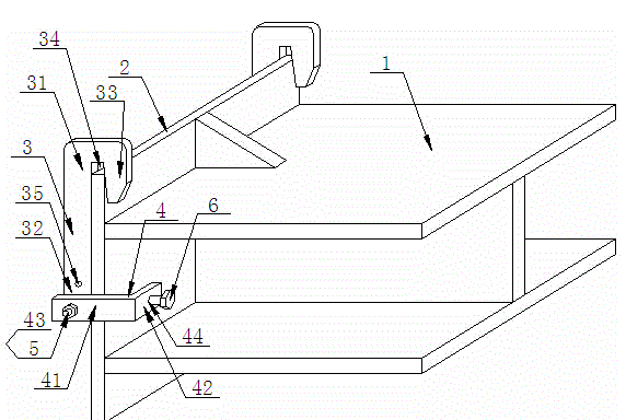
[0016] Such as figure 1 As shown, the structural diagram of the anti-deformation clamp for the steel beam structural plate in this embodiment. The anti-deformation clamp for the steel beam structure plate of this embodiment includes: an anti-deformation main body steel plate 3, the anti-deformation main body steel plate 3 includes a first clamping end 31 for clamping and fixing the edge of the structural plate 2, and a clamping Holding the second clamping end 32 in the middle of the fixed structural plate 2, the first clamping end 31 is provided with a hook portion 33, and a wedge-shaped clamping portion is provided between the hook portion 33 and the anti-deformation main steel plate 3 Slot 34, the second clamping end 32 is provided with a first connecting screw hole 35; specifically, there may be several first connecting screw holes 35, so as to be selected and used according to actual needs. The movable clamping steel plate 4 includes a connecting portion 41 and a fixed portion 42, the connecting portion 41 and the fixed portion 42 are perpendicular to each other, and the connecting portion 41 is provided with a second connecting screw hole 43 , The fixing portion is provided with a third connecting screw hole 44; the first connecting screw hole 35 and the second connecting screw hole 43 are connected by a connecting bolt 5, and the third connecting screw hole 44 is provided with Fixing bolt 6; Specifically, preferably, the fixing bolt 6 is coplanar with the anti-deformation main steel plate 3, so as to improve the clamping effect.
[0017] When working, first process the groove position at the corresponding position of the structural plate 2 according to actual needs, and then initially connect and fix the two ends of the steel beam 1 made of H-shaped steel with the structural plate 2 by spot welding, and then install this embodiment The described anti-deformation fixture for the steel beam structural plate: lay the steel beam 1 flat, make the structural plate 2 in a vertical state, and then place the anti-deformation main steel plate 3 on one side of the structural plate 2 and place the edge of the structural plate 2 The top is placed in the wedge-shaped clamping groove 34, and then the connecting portion 41 of the movable clamping steel plate 4 and the second clamping end 32 of the anti-deformation main steel plate are connected by the connecting bolt 5, and then the fixed portion of the movable clamping steel plate 4 42 is placed on one side of the structural plate 2 facing the steel beam 1, and the second clamping end 32 of the anti-deformation main steel plate 3 is clamped and fixed by the interaction force of the fixing bolt 6 and the anti-deformation main steel plate 3; An anti-deformation clamp for the steel beam structure plate described in this embodiment is also installed and fixed on the other side edge of the plate 2. Specifically, it can also be between two anti-deformation clamps for the steel beam structure plate described in this embodiment. A triangular support block is spot welded between the structural plate 2 and the upper wing plate of the steel beam 1 made of H-shaped steel. Then the overall reinforcement welding operation can be carried out. Since the anti-deformation main steel plate 3 on the side of the structural plate 2 facing away from the steel beam 1 has a fixed force on the structural plate 2, which can prevent it from being grooved during the welding operation. C-shaped bending deformation occurs toward the steel beam 1 side due to factors such as processing and welding high temperature.
[0018] The above content is a detailed description of the present invention in conjunction with specific embodiments, and it cannot be considered that the specific implementation of the present invention is limited to these descriptions. For those skilled in the art to which the present invention belongs, without departing from the concept of the present invention, several simple deductions or substitutions can be made, which should be regarded as falling within the protection scope of the present invention.

PUM

no PUM

Description & Claims & Application Information

We can also present the details of the Description, Claims and Application information to help users get a comprehensive understanding of the technical details of the patent, such as background art, summary of invention, brief description of drawings, description of embodiments, and other original content. On the other hand, users can also determine the specific scope of protection of the technology through the list of claims; as well as understand the changes in the life cycle of the technology with the presentation of the patent timeline. Login to view more.

Similar technology patents

Ice cream self-service vending machine

Owner:南京热冰科技有限公司

Operating terminal for air conditioner

ActiveCN103363619AReduce operating costs
Owner:MITSUBISHI ELECTRIC CORP

Classification and recommendation of technical efficacy words

  • Reduce operating costs
  • Reduce labor intensity

Method for intelligent automatic identification of transmission circuit parts

Owner:INFORMATION COMM COMPANY STATE GRID SHANDONG ELECTRIC POWER +2

City regional railway signal system and control method thereof

Owner:CHINA RAILWAY SIYUAN SURVEY & DESIGN GRP

Railway bearing intelligent on-line detection method and its device

InactiveCN101290265AReduce labor intensity
Owner:洛阳铭昊测控科技有限公司
Why Eureka
Try Eureka