
Rotor wing rotating signal collecting device for helicopter model

A helicopter model and rotating signal technology, which is applied to ground devices, aircraft parts, transportation and packaging, etc., can solve the problems of signal pollution, acquisition equipment installation, submersion, etc., and achieve the effect of avoiding signal attenuation and coupling capacitance, and improving accuracy

Active Publication Date: 2015-07-29
CHINA HELICOPTER RES & DEV INST
View PDF5 Cites 13 Cited by
  • Summary
  • Abstract
  • Description
  • Claims
  • Application Information

AI Technical Summary

Problems solved by technology

[0003] Conventional helicopter model rotor tests are usually limited by the size of the hub, large overload centrifugal force, and dynamic balance. Conventional acquisition equipment cannot be installed on the hub, but such as: tie rod load, blade flapping load, blade shimmy Weak signals at the microvolt level such as loads are transmitted to the remote ground acquisition equipment through slip rings and long wires. Due to the signal attenuation and coupling capacitance in the transmission of slip rings and long wires, and the interference by the strong electromagnetic field of the power system during transmission , the signals measured by ground acquisition equipment are often polluted or completely submerged in interference signals and cannot be used

Method used


Image

  • Rotor wing rotating signal collecting device for helicopter model
  • Rotor wing rotating signal collecting device for helicopter model
  • Rotor wing rotating signal collecting device for helicopter model

Examples


Embodiment 1

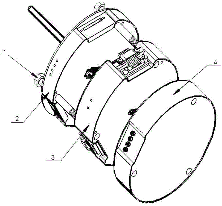
[0025] Such as figure 1 As shown, a helicopter model rotor rotation signal acquisition device includes, from top to bottom, a data acquisition and transmission module 2, a signal conditioning module 3 and a battery module 4, and the three modules are all in the shape of a round cake, wherein the data acquisition and transmission module The external dimension is φ140mm (diameter)×22mm (length), and the weight is 340 grams. The external dimension of the signal conditioning module is φ140mm (diameter)×35mm (length), and the weight is 450 grams. The external dimension of the battery module is φ140mm (diameter)×31mm (length), weight is 550 grams.

[0026] An antenna 5 is installed on the upper surface of the data acquisition and transmitting module 2, a signal input connector 7 protrudes from the center of the lower surface, and a signal output connector 15 is recessed in the center of the upper surface of the signal conditioning module 3, and the signal output connector 15 is conn...

Embodiment 2

[0036] Similar to Embodiment 1, the difference is that there are three screw holes near the edge of the data acquisition and transmission module 2, the signal conditioning module 3 and the battery module 4, and the data acquisition and transmission module, the signal conditioning module and the signal conditioning module are connected by a long bolt 1 The module and the battery module are connected in series and fixed. The bolts are φ8mm (diameter) × 90mm (length), which are used to run through the entire helicopter model rotor rotation signal acquisition device. The weight is 80 grams, and there are 3 pieces in total, which are evenly arranged at 120°.

[0037]The device is installed on the hub of the model rotor, as close as possible to weak signal sources at the microvolt level such as tie rod load, blade flapping load, blade shimmy load, etc., and then completes power supply, weak signal conditioning, data acquisition and monitoring of the device by itself. Wireless transmi...


PUM


Abstract

The invention relates to a rotor wing rotating signal collecting device for a helicopter model, belonging to the field of rotor wing tests of the helicopter model. The rotor wing rotating signal collecting device comprises a data collecting-transmitting module (2), a signal conditioning module (3) and a battery module (4), wherein an external signal is amplified and filtered by the signal conditioning module (3), and is subjected to digital-to-analog conversion and transmitted by the data collecting-transmitting module (2). According to the rotor wing rotating signal collecting device for the helicopter model, the data collecting-transmitting module (2), the signal conditioning module (3) and the battery module (4) are connected through signal lead wires and power supply lead wires, are fixed through long bolts, and are used for supplying power for the device, conditioning weak signals, and collecting and wirelessly transmitting data through themselves, so that the problem of data invalidation caused by signal attenuation and coupling capacitance due to slip ring and long lead wire transmission as well as interference of a strong electromagnetic field of a power system in the transmission process is effectively prevented, and the accuracy of measuring an extremely weak signal of a rotor wing of the helicopter model can be effectively improved.

Description

technical field [0001] The invention relates to the field of helicopter model rotor tests, in particular to a helicopter model signal acquisition device. Background technique [0002] Helicopter model rotor rotation signal acquisition is an important technology in the helicopter model rotor test, and it is the premise to accurately obtain microvolt-level weak rotation signals such as model blade tie rod load, blade flapping load, and blade shimmy load. [0003] Conventional helicopter model rotor tests are usually limited by the size of the hub, large overload centrifugal force, and dynamic balance. Conventional acquisition equipment cannot be installed on the hub, but such as: tie rod load, blade flapping load, blade shimmy Weak signals at the microvolt level such as loads are transmitted to the remote ground acquisition equipment through slip rings and long wires. Due to the signal attenuation and coupling capacitance in the transmission of slip rings and long wires, and t...

Claims


Application Information

Patent Timeline
Patent Type & Authority Applications(China)
IPC IPC(8): B64F5/00B64F5/60
Inventor 刘正江陈焕孙伟陈卫星金小强邓建军李新民王江华
Owner CHINA HELICOPTER RES & DEV INST
Learn More