A kind of interlocking locking mechanism of the wire loop warehouse of the steel bar binding machine

A strapping machine and interlocking technology, applied in building construction, building material processing, construction, etc., can solve the problem of difficulty in ensuring the reliability and life of the machine, no waterproof and dustproof functions, and the failure rate of steel strapping machines. Improve and other problems, to achieve the effect of simple structure, reduced operation difficulty, and reduced manufacturing difficulty

Active Publication Date: 2017-08-25
GUANGDONG SHUNDE HUAYAN ELECTRONICS TECH CO LTD
View PDF7 Cites 1 Cited by
  • Summary
  • Abstract
  • Description
  • Claims
  • Application Information

AI Technical Summary

Problems solved by technology

[0002] The steel bar binding machines on the market are all tools for outdoor use. They need to be used under dusty, humid or rainy conditions. However, the current steel bar binding machines do not have waterproof and dustproof functions, and the coil warehouses are all exposed. Yes, under such conditions of use, the exposure of the wire loop warehouse will cause the iron wire to rust, and at the same time, water, dust and sundries will be brought into the machine body, which will greatly increase the failure rate of the steel bar binding machine, and it may also be in the steel bar binding machine The human body is injured when it comes into contact with the high-speed wire loop during work
[0003] In addition, since most of the wire loop warehouses on the market are composed of multiple parts, it is difficult to guarantee the reliability and life of the machine, and it also makes the replacement process of the wire loop more complicated and difficult to operate

Method used


Image

  • A kind of interlocking locking mechanism of the wire loop warehouse of the steel bar binding machine
  • A kind of interlocking locking mechanism of the wire loop warehouse of the steel bar binding machine
  • A kind of interlocking locking mechanism of the wire loop warehouse of the steel bar binding machine

Examples


Embodiment 1

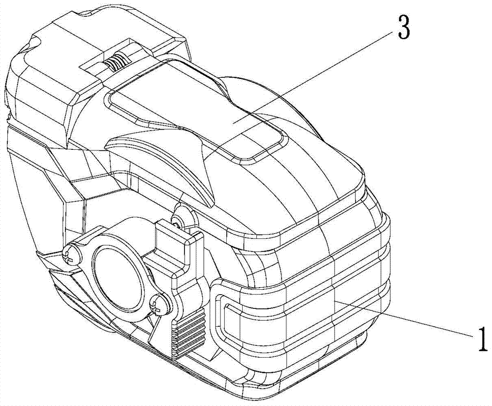
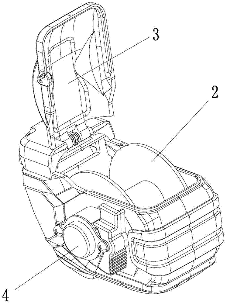
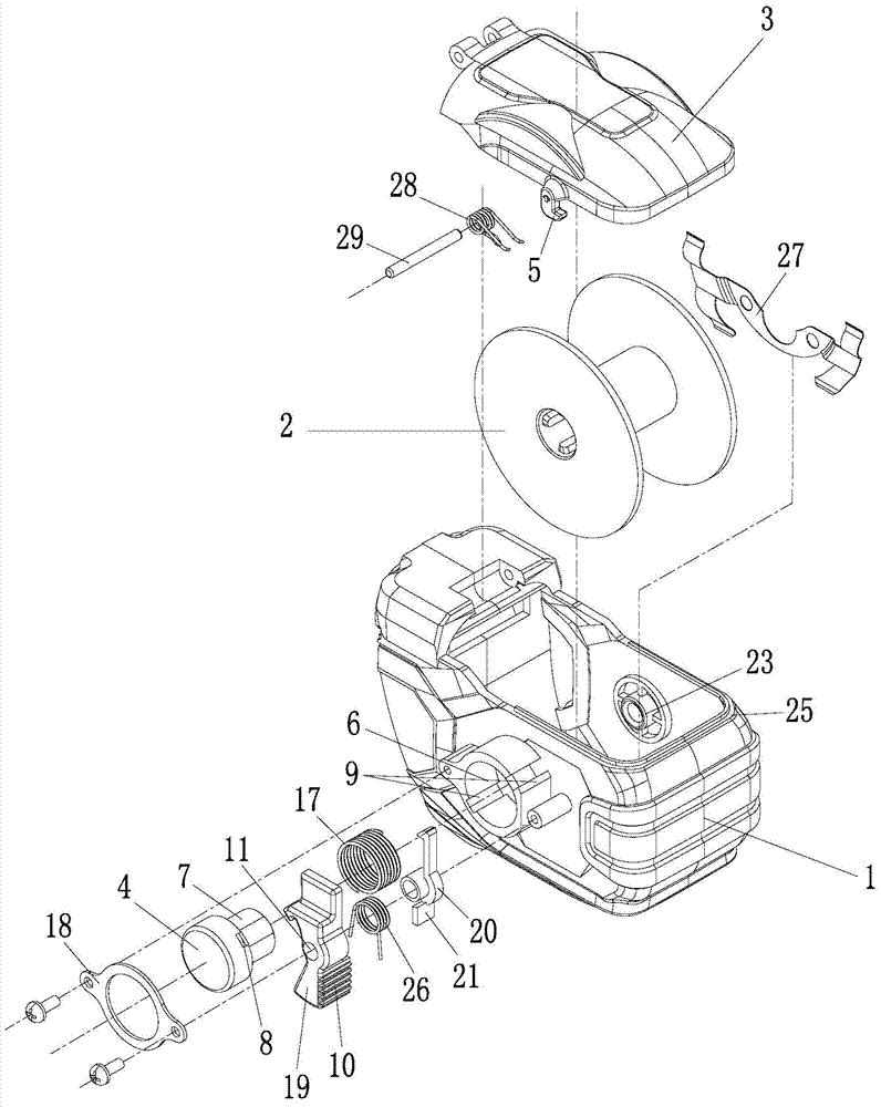
[0032] A wire loop bin linkage locking mechanism for a steel bar binding machine, comprising a wire hoop bin 1, a wire hoop 2, a wire hoop bin cover 3, a wire hoop positioning button 4, a torsion spring 26 and an unlock button, the wire hoop bin cover is hinged On the wire loop bin, the wire loop is placed in the wire loop bin, a hook 5 protrudes from one side of the wire loop bin cover, and a button cavity 6 is provided at a position corresponding to the hook in the wire loop bin, and the wire loop The positioning button axially protrudes with a movable wire ring positioning pin 7, and the radial direction of the wire ring positioning button shaft protrudes with a stopper 8, and a through hole 30 is opened in the button cavity, and the wire ring positioning button is arranged in the button cavity Among them, the active wire ring positioning pin is connected to the drum of the wire ring through the through hole, and the button cavity is provided with a guide groove 9 correspond...


PUM


Abstract

The invention discloses a wire loop bin linkage locking mechanism of a steel bar binding machine, comprising a wire hoop bin, a wire hoop, a wire hoop positioning button, a torsion spring and an unlocking button. The wire hoop bin is provided with a button cavity and a wire hoop positioning button There is a movable coil positioning pin protruding axially, and a stopper protrudes radially from the shaft of the coil positioning button. There is a through hole in the button cavity. The coil positioning button is set in the button cavity, and the movable coil positioning pin passes The through hole is connected to the drum of the wire loop, and the button cavity is provided with a guide groove corresponding to the position of the stopper, and the stopper is connected in the guide groove; the unlocking button is provided with a pressing part, a hinged part and a restricting part in sequence, and the unlocking button is hinged. The part is hinged on the coil bin, the torsion spring is arranged at the joint between the hinge part and the coil bin, and the restricting part includes a blocking part for preventing the block from sliding outward. The invention can lock the wire loop put into the wire loop warehouse with one key, so that it can rotate and work stably in the wire loop warehouse.

Description

technical field [0001] The invention relates to a steel bar binding machine, in particular to a wire coil bin interlocking locking mechanism of the steel bar binding machine. Background technique [0002] The steel bar binding machines on the market are all tools for outdoor use, and need to be used in dusty, humid or rainy conditions. However, the current steel bar binding machines do not have waterproof and dustproof functions, and the coil warehouses are all exposed. Yes, under such conditions of use, the exposure of the wire loop warehouse will cause the iron wire to rust, and at the same time, water, dust and sundries will be brought into the body, which will greatly increase the failure rate of the steel bar binding machine, and it may also be in the steel bar binding machine. The human body is injured when it comes into contact with the high-speed wire loop during work. [0003] In addition, since most wire coil warehouses on the market are composed of multiple parts...

Claims


Application Information

Patent Timeline
Patent Type & Authority Patents(China)
IPC IPC(8): E04G21/12
Inventor 易映国罗泳杨李移清肖秀南
Owner GUANGDONG SHUNDE HUAYAN ELECTRONICS TECH CO LTD
Why Eureka
Try Eureka