Novel partial pressure injection tool

A partial pressure and tool technology, which is applied in wellbore/well components, production fluid, earthwork drilling and production, etc., can solve the problem of high viscosity loss, achieve small viscosity loss, reduce shear damage, and reduce viscosity loss.

Active Publication Date: 2015-07-29
NORTHEAST GASOLINEEUM UNIV
View PDF7 Cites 8 Cited by
  • Summary
  • Abstract
  • Description
  • Claims
  • Application Information

AI Technical Summary

Problems solved by technology

[0004] The purpose of the present invention is to provide a new partial pressure injection tool, which is used to solve the problem that the existing injection tools used when injecting polymer or injecting ternary composite solutions usually produce a large pressure drop. Problems with high viscosity loss

Method used


Image

  • Novel partial pressure injection tool
  • Novel partial pressure injection tool
  • Novel partial pressure injection tool

Examples


Embodiment Construction

[0020] The present invention is described further below:

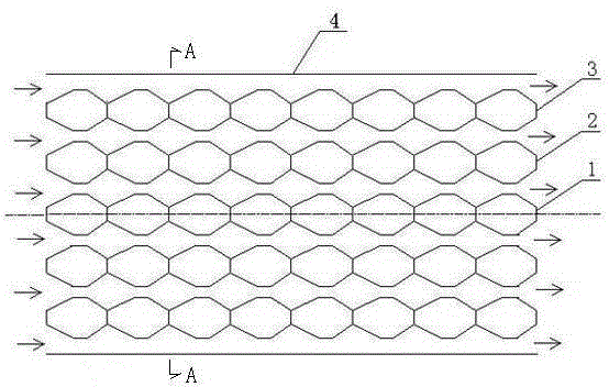
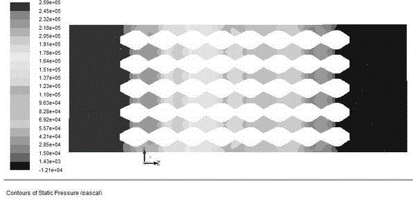
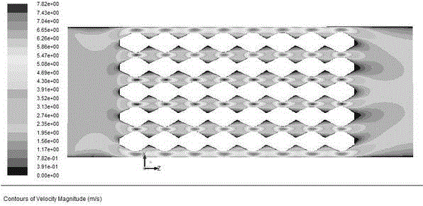
[0021] combine figure 1 , Image 6 As shown, this new partial pressure injection tool is a pressure-reducing groove composed of a throttle core 1, an inner throttle ring column 2, an outer throttle ring column 3, and an outer cylinder 4 coaxially set together from the inside to the outside, that is, The inner throttle ring column 2 surrounds the throttle core 1, the outer throttle ring column 3 surrounds the inner throttle ring column 2, the outer cylinder 4 surrounds the outer throttle ring column 3, the throttle core 1, the inner throttle Both the ring column 2 and the outer throttling ring column 3 have variable cross-sections. Outer cylinder 4 inner diameters are 20mm, (outer cylinder inner diameter sees Figure 5 Middle d10), the annular gap between the outer cylinder 4 and the outer throttle ring column 3 is 0.9mm, the annular gap between the inner throttle ring column 2 and the throttle core 1 is 0.8mm, the o...


PUM


Abstract

The invention relates to a novel partial pressure injection tool. The novel partial pressure injection tool is a depressurizing groove formed by coaxially sheathing a throttling core, an inner throttling ring pillar, an outer throttling ring pillar and an outer cylinder from inside to outside; the throttling core, the inner throttling ring pillar, and the outer throttling ring pillar are variable cross-section; the throttling core is formed by orderly connecting eight spindle shaped grooves with equal groove distance; the shape of the inner throttling ring pillar is the same as that of the outer throttling ring pillar; the inner throttling ring pillar and the outer throttling ring pillar are formed by orderly connecting eight spindle shaped ring grooves with equal groove distance; the spindle shaped grooves of the throttling core is corresponding to the spindle shaped ring grooves of the inner throttling ring pillar one by one, and the spindle ring grooves of the inner throttling ring pillar are corresponding to the spindle shaped ring grooves of the outer throttling ring pillar one by one; the longitudinal section of the spindle shaped ring grooves along the length direction is in the shape of spindle, and the longitudinal section of the spindle shaped grooves of the throttling core along the length direction is also in the shape of spindle; an annular gap between the inner throttling ring pillar and the throttling core is equal to the ring gap between the outer throttling ring pillar and the inner throttling ring pillar; the annular gap between the outer cylinder and the outer throttling ring pillar is slightly more than the annular gap. The novel partial pressure injection tool reduces the shear failure effect on ternary composite solution, and reduces the viscosity loss of flowing through the depressurizing groove.

Description

technical field [0001] The invention relates to an injection tool used for polymer injection or ternary compound solution injection in an oil field, in particular to a novel partial pressure injection tool. Background technique [0002] As oilfield development enters the later stage, most oilfields use polymer flooding or ASP flooding to increase oilfield production. However, when injecting polymer or ternary compound solution, the structure of the injection tool will affect the change of the pressure and viscosity of the fluid. The general injection tool usually produces a large pressure drop and high viscosity loss, which makes the polymer solution or ternary compound solution to reduce the range of enhanced oil recovery. Especially when injecting into high-permeability formations, the effect of enhanced oil recovery is greatly affected after being sheared by the injection tool. [0003] The decompression principle of the decompression groove mainly realizes the accelera...

Claims


Application Information

Patent Timeline
Patent Type & Authority Applications(China)
IPC IPC(8): E21B43/22
CPCE21B43/16
Inventor 黄斌傅程刘进祥赵法军王春生马文国
Owner NORTHEAST GASOLINEEUM UNIV
Why Eureka
Try Eureka