

An automobile power and transmission system performance test bench
A test bench and transmission system technology, which is applied in the field of automotive power and transmission system performance test benches and test benches, can solve the problems that the braking system cannot be integrated, and the tire meshing characteristics cannot be simulated, so as to facilitate large-scale promotion The application and system dynamic characteristics are accurate and the design is reasonable
- Summary
- Abstract
- Description
- Claims
- Application Information
AI Technical Summary
Problems solved by technology
Method used
Image

Examples
Embodiment 1
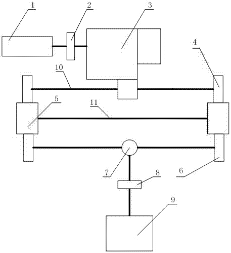
[0016] Embodiment 1: see figure 1 , a vehicle power and transmission system performance test bench, the test bench includes a power source 1, an input end torque sensor 2, a measured object 3, a drive end half shaft 10, a front wheel 4, a flywheel system 5, a rear end Wheel 6, output end torque sensor 8 and load dynamometer 9, the input end torque sensor 2 is arranged between the power source 1 and the measured object 3, one side of the flywheel system is provided with the front wheel 4, the described The other side of the flywheel system is provided with a rear wheel 6, and the load dynamometer 9 is connected to the rear wheel through an output torque sensor 8. The power source 1 is an engine or a drive dynamometer, and the measured object 3 is a transmission or a hybrid power system. In this technical solution, the drive dynamometer is connected to the input end torque sensor 2 through a flange, and the input end torque sensor 2. Connect to the input end of the tested objec...
Embodiment 2
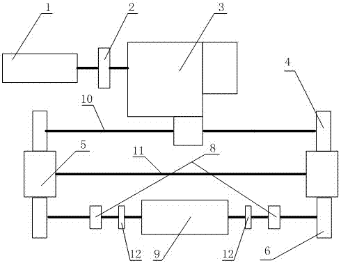
[0017] Example 2: see figure 2 , as an improvement of the present invention, the test bench also includes a coupling 12, and the coupling 12 is arranged between the output end torque sensor 8 and the load dynamometer; the power source 1 is the driving dynamometer The torque sensor 2 at the input end is connected through the flange, and the torque sensor 2 at the input end is connected with the input end of the measured object 3 through the flange. The measured object 3 is installed on the support fixed on the iron floor. The shaft 10 and the front wheel 4 are connected to the double output port of the transmission according to the installation method of the original car. The wheel is suspended at a certain distance from the iron floor and meshed with the flywheel. The flywheel system 5 on one side is solidly connected into one body through the flywheel shaft 11, and the flywheel shaft 11 is fixed on the iron floor through the bearing seat. The wheels 6 are suspended and inst...
Embodiment 3
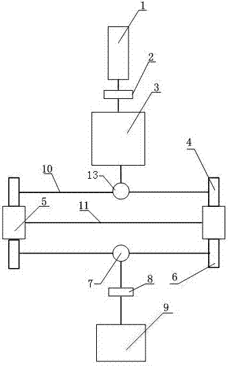
[0018] Example 3; see image 3 , this embodiment is the embodiment of the object to be measured with front and rear drive. In this technical solution, an integrated axle system is arranged in the middle of the half shaft of the front wheel 4, and the power source 1 drives the dynamometer through the flange and the input The end torque sensor 2 is connected, the input end torque sensor 2 is connected with the input end of the measured object 3 through the flange, the front wheel 4 is installed on both sides of the integrated front axle 13, the measured object 3 is connected with the integrated rear vehicle through the flange The input end of the bridge 7 is connected, the front wheel 4 is meshed with the flywheel system 5, and the tire and the outer circumference of the flywheel system are prevented from slipping through the pre-compression force. The seat is fixed on the iron floor. At the same time, the other side of the flywheel system 5 engages with a pair of rear-end whee...
PUM
 Abstract
Description
Claims
Application Information