
Carbonatite microflow simulating method and device

A carbonate rock and flow simulation technology, applied in special data processing applications, instruments, electrical digital data processing, etc.

Inactive Publication Date: 2015-07-29
CHINA UNIV OF PETROLEUM (BEIJING)
View PDF3 Cites 10 Cited by
  • Summary
  • Abstract
  • Description
  • Claims
  • Application Information

AI Technical Summary

Problems solved by technology

The disadvantage of this analysis method is that it takes a long time and errors are prone to occur in the experimental process.
[0005] 1. The measurement data of the displacement experiment requires professional technicians to interpret, and it is highly dependent on the technical level and experience of the operator. The accuracy of the instrument will directly affect the quality of the displacement result; in actual work, due to the operator, camera parameter settings, etc. There may be differences in the analysis results;
[0006] 2. Long measurement time
Due to the poor connectivity and strong heterogeneity of carbonate rock, it takes a long time to do a set of displacement experiments. If there is an error, it needs to be re-measured. will cause test errors;
[0007] 3. During the displacement process, only some real-time data, time and flow can be recorded, and the displacement process cannot be observed dynamically in real time, and the real fluid flow law cannot be reflected
[0011] 1. During the mercury injection experiment, the mercury used is poisonous and will cause harm to the human body and the environment;
[0012] 2. The pore structure characteristics of the rock obtained by the mercury injection method is an average parameter, and the quantitative distribution characteristics of pore throats of different sizes cannot be obtained;
[0013] 3. During the mercury injection experiment, the mercury injection process will destroy the original pores and the clay minerals inside, which cannot reflect the real rock pore structure characteristics
[0014] 4. During the mercury injection experiment, only some real-time data can be recorded, and the displacement process cannot be observed dynamically in real time, and the real fluid flow law cannot be reflected

Method used


Image

  • Carbonatite microflow simulating method and device
  • Carbonatite microflow simulating method and device
  • Carbonatite microflow simulating method and device

Examples


Embodiment Construction

[0075] In order to make the purpose, technical solutions and advantages of the embodiments of the present invention more clear, the embodiments of the present invention will be further described in detail below in conjunction with the accompanying drawings. Here, the exemplary embodiments and descriptions of the present invention are used to explain the present invention, but not to limit the present invention.

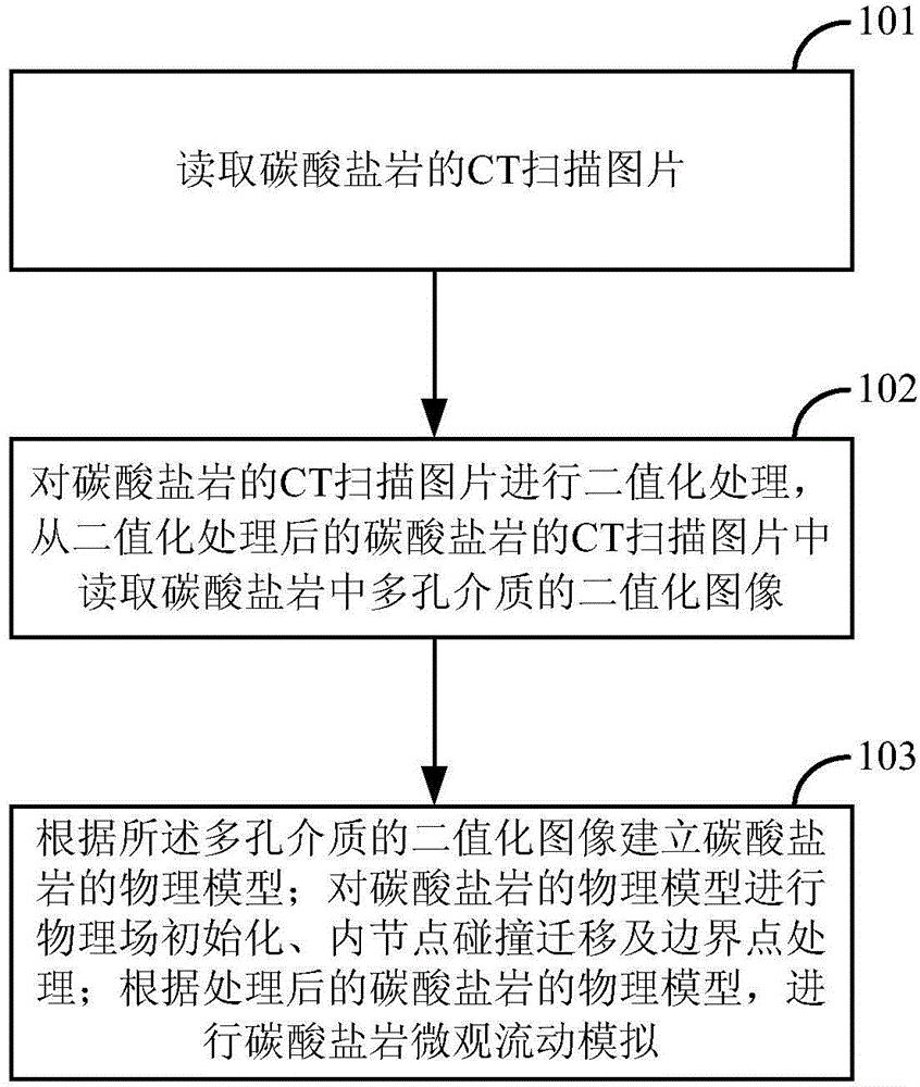
[0076] Aiming at the shortcomings of the current conventional and unconventional core flow simulation time and large error, in the technical solution provided in the embodiment of the present invention, through image processing technology, combined with program design, using CT scanning images, using carbonate rock CT The scanning image is used as an example to simulate the flow of fluid in carbonate rock salt, which provides a reliable method and technology for the development of carbonate rock reservoirs. The specific implementation can be as follows:

[0077] fig...


PUM


Abstract

The invention discloses a carbonatite microflow simulating method and device. The method comprises the steps of reading a CT scanning photo of carbonatite; performing binaryzation treatment for the CT scanning photo of carbonatite; reading a binaryzation image of the porous medium in carbonatite from the CT scanning photo of carbonatite after binaryzation treatment; building a physical model of carbonatite according to the binaryzation image of the porous medium; performing physical field initializing, inner node collision migration and boundary point treatment for the physical model of carbonatite; performing carbonatite microflow simulating according to the treated physical model of carbonatite. The method can quickly and accurately to perform carbonatite microflow simulating.

Description

technical field [0001] The invention relates to the technical field of oilfield exploitation, in particular to a carbonate rock microscopic flow simulation method and device. Background technique [0002] For the research on the development of pores, vugs and fractures in carbonate rock reservoirs, there are few research methods and knowledge on the microscopic flow of pores, vugs and fractures in carbonate rock reservoirs, and conventional displacement experiments, mercury injection It is difficult to accurately and quickly simulate the microscopic flow of carbonate rocks. Next, the displacement experiment and the mercury porosimetry will be described. [0003] 1. One of the microscopic analysis techniques in the study of flow law: displacement experiment. [0004] The displacement experiment is to fill the core with saturated brine, then put it into the core holder, set the flow rate, measure the pressure at the inlet end of the core under the set flow rate, and measure ...

Claims


Application Information

Patent Timeline
IPC IPC(8): G06F17/50
Inventor 董平川邓兴梁于红枫张正红董睿涛杨书吴子森钟小葵黎丽丽
Owner CHINA UNIV OF PETROLEUM (BEIJING)
Learn More