A controllable electromagnetic tripping device and tripping method with added magnetic conductor

A technology of electromagnetic tripping and magnetic conductor, applied in emergency protection devices, circuits, electrical components, etc., to achieve the effect of reducing air gap, sensitive and rapid tripping action, good operability and adjustability

Active Publication Date: 2017-03-08
NANJING DAQO ELECTRICAL INST CO LTD
View PDF8 Cites 0 Cited by
  • Summary
  • Abstract
  • Description
  • Claims
  • Application Information

AI Technical Summary

Problems solved by technology

This application provides a solution to optimize the short-circuit breaking performance of the trip device by adjusting the air gap of the moving and static iron cores, but the short-circuit trip device of this application still needs further improvement in terms of operability and adjustability

Method used


Image

  • A controllable electromagnetic tripping device and tripping method with added magnetic conductor
  • A controllable electromagnetic tripping device and tripping method with added magnetic conductor
  • A controllable electromagnetic tripping device and tripping method with added magnetic conductor

Examples


Embodiment 1

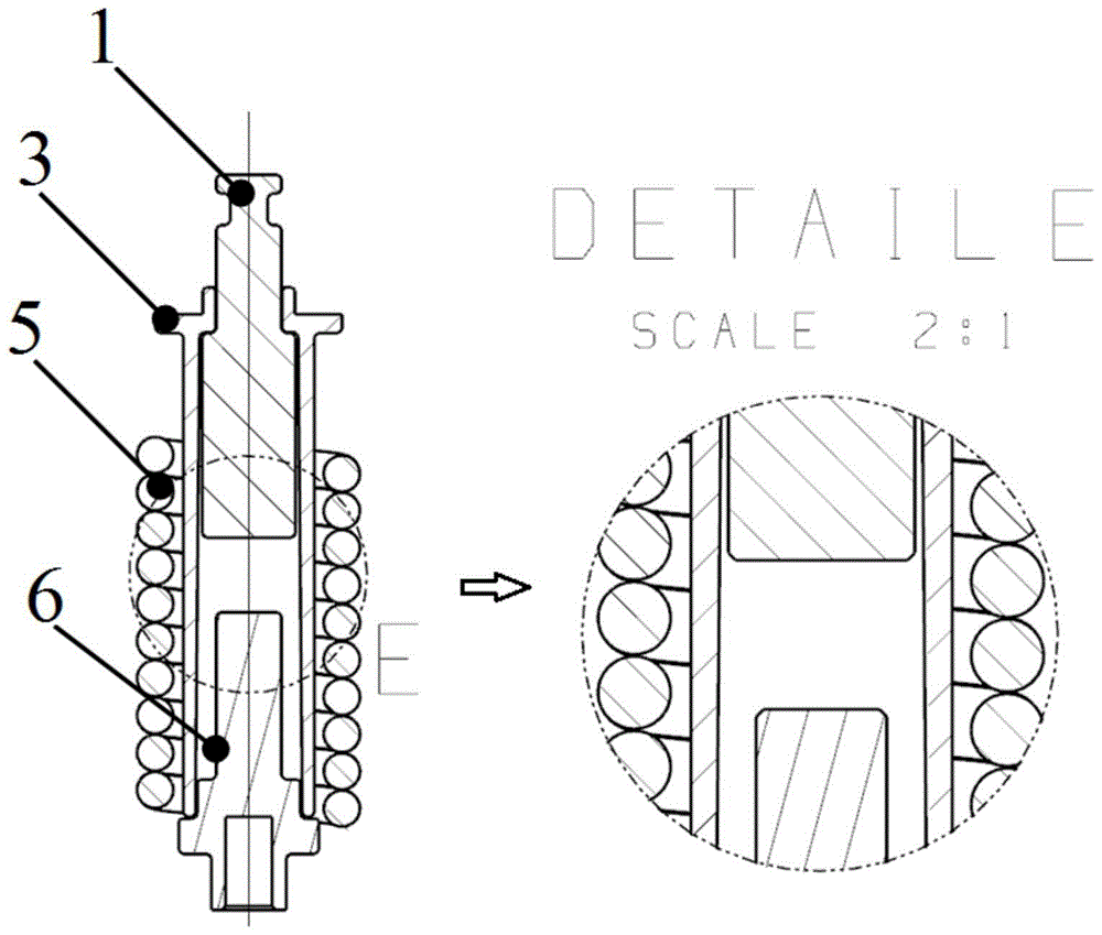
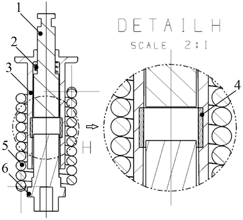
[0032] With reference to the accompanying drawings, a controllable electromagnetic tripping device with a magnetic conductor added in this embodiment includes a moving iron core 1 and a static iron core 6 made of ferromagnetic material, an outer sleeve 3 made of non-magnetic conductive material, and The coil 5 is made of conductors, the outer sleeve 3 is sleeved on the outside of the movable iron core 1 and the static iron core 6, and the movable iron core 1 reciprocates inside the outer sleeve 3, approaching or away from the static iron core 6 in a straight line, the coil 5 is wound on the outside of the outer sleeve 3. In this embodiment, a magnetic conductor is added between the moving iron core 1 and the static iron core 6 . The magnetic conductor is made of ferromagnetic material (such as No. 10 steel, etc.). Magnet, adjust the relative position of the magnetic conductor and the moving iron core 1 and the static iron core 6, which can realize the control of a wide range o...

Embodiment 2

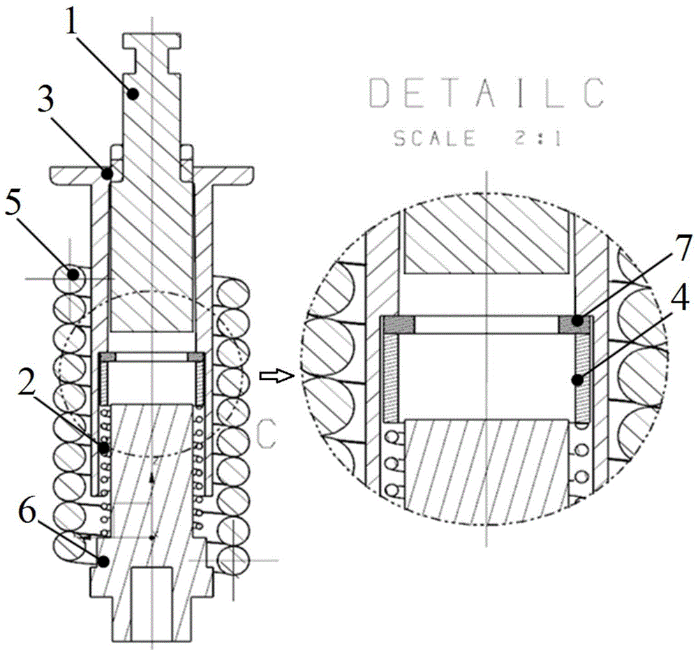
[0041] see image 3 , this embodiment is another solution for adding a magnetic conductor. Its basic structure is the same as that of Embodiment 1, the difference is: the outer sleeve 3 is provided with steps inside, the upper aperture of the outer sleeve 3 is smaller than the lower aperture, the magnetic conductor still adopts the cylindrical magnetic conductor sleeve 4, and the magnetic conductor is used. One end of the sleeve 4 abuts against the step set by the outer sleeve 3 through a non-magnetic conductive gasket 7. The non-magnetic conductive gasket 7 can be selected from austenitic steel and other materials with strong toughness. The structure can be a ring or a solid gasket. Its inner diameter is smaller than the outer diameter of the moving iron core 1, specifically, it can reliably drive the magnetic conductor sleeve 4 to move. And its relative initial position with the iron core is only determined by the outer sleeve 3 controlled by the external structure. The ot...


PUM


Abstract

The invention discloses a magnetizer-added controllable electromagnetic trip device and a tripping method and belongs to the technical field of electromagnetic trip devices. The device comprises a movable iron core, an outer sleeve, a coil and a statistic iron core; the outer sleeve sleeves the movable iron core and the statistic iron core; the movable iron core performs linear motions relative to the statistic iron core; the coil wraps the outer sleeve; a magnetizer is added between the movable iron core and the statistic iron core, and the position of the magnetizer corresponding to the movable iron core and the statistic iron core is adjustable. The air gap between the movable iron core and the statistic iron core is changed by adjusting the position of the magnetizer corresponding to the movable iron core and the statistic iron core; the rated current can be controlled in the certain range, the purpose of providing instantaneous short circuit protection for circuit breakers with various rated currents is achieved, and the higher maneuverability and adjustability are provided.

Description

technical field [0001] The invention relates to a controllable electromagnetic tripping device, which is mainly used for a multi-position controllable electromagnetic tripping device, and can also be used in other automation fields where electromagnets are used as driving or executing components. Background technique [0002] As a drive or actuator, electromagnets are widely used in automation equipment because of their good working characteristics and the ability to convert electromagnetic energy into mechanical energy. Magnetic trip units based on the principle of electromagnets are mainly used for low-voltage circuit breakers. [0003] see figure 1 , The traditional magnetic release is mainly composed of a moving iron core 1, a coil 5, a static iron core 6 and an outer sleeve 3 which is set outside the moving and static iron cores and is made of plastic material. It changes the air gap by changing the relative position of the moving iron core 1 and the static iron core ...

Claims


Application Information

Patent Timeline
Patent Type & Authority Patents(China)
IPC IPC(8): H01H71/24
CPCH01H71/24H01H71/2463
Inventor 于超
Owner NANJING DAQO ELECTRICAL INST CO LTD
Why Eureka
Try Eureka