
EMI filter network with impedance mismatching network

A technology of impedance mismatch and filter, applied in the electronic field, can solve problems such as poor working results

Inactive Publication Date: 2015-07-29
NANJING UNIV OF AERONAUTICS & ASTRONAUTICS
View PDF3 Cites 5 Cited by
  • Summary
  • Abstract
  • Description
  • Claims
  • Application Information

AI Technical Summary

Problems solved by technology

However, this type of EMI filter is often affected by the mismatch between the noise source impedance and the load impedance, resulting in poor performance

Method used


Image

  • EMI filter network with impedance mismatching network
  • EMI filter network with impedance mismatching network
  • EMI filter network with impedance mismatching network

Examples


Embodiment Construction

[0036] The present invention will be further described below in conjunction with the accompanying drawings.

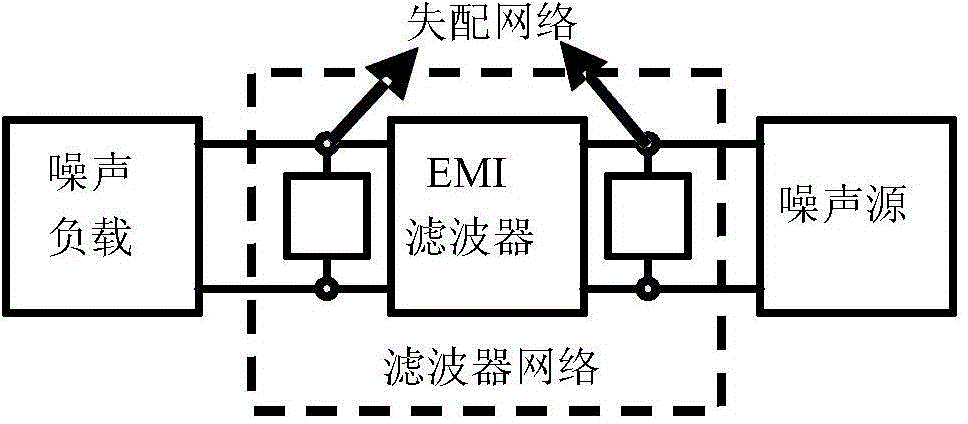
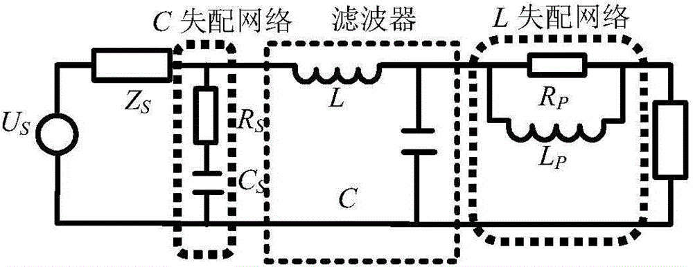
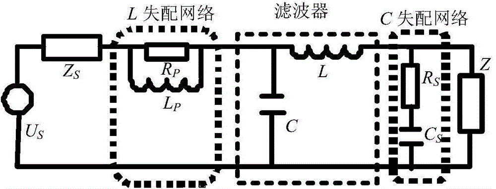
[0037] Such as figure 1 Shown is an EMI filter network with an impedance mismatch network. On the basis of the original insertion loss of the EMI filter, the impedance mismatch degree of the filter port is increased by accessing the impedance mismatch network to provide a larger The reflection loss can achieve the purpose of improving the performance of the filter. It includes two parts: mismatch network and EMI filter. The EMI filter is mainly composed of inductor L and capacitor C. The mismatch network includes L-type mismatch network and C-type mismatch network. The L-type mismatch network is mainly composed of resistor R P and inductance L P Composed in parallel, the C-type mismatch network is mainly composed of resistors R S and capacitance C S The L-type mismatch network is connected in series with the high-impedance end of the EMI filter, and the C-type mism...


PUM


Abstract

The invention discloses a design method for an EMI filter network with an impedance mismatching network. The EMI filter network with the impedance mismatching network comprises two parts of the mismatching network and an EMI filter; the EMI filter consists of an inductor L and a capacitor C; the mismatching network comprises an L-type mismatching network and a C-type mismatching network; the L-type mismatching network consists of a resistor RP and an inductor LP which are parallelly connected; the C-type mismatching network consists of a resistor RS and a capacitor CS which are serially connected; the L-type mismatching network is serially connected with the high impedance end of the EMI filter; the C-type mismatching network is parallelly connected with the low impedance end of the EMI filter; and the attenuation of the EMI noise by the EMI filter network is divided to two parts of the insertion loss brought by own EMI filter and the reflection loss after the EMI filter is connected to the mismatching network. High frequency impedance of the noise source and the high frequency impedance of the filter input port after connecting the mismatching network are located in the serious mismatching state, the larger reflection loss is generated to the EMI signal, and the EMI signal from the source end is effectively blocked to be transmitted into other electronic devices.

Description

technical field [0001] The invention belongs to the field of electronic technology, in particular to an EMI filter network design method with an impedance mismatch network. Background technique [0002] With the increase of the operating frequency of power electronic converters, the seriousness of the conducted electromagnetic interference of power converters has become increasingly prominent. In order to prevent the mutual interference between the power converter and other equipment, the power converter must pass the relevant electromagnetic compatibility (EMC) standard test before being put on the market. EMI filter is one of the important means to suppress conducted noise, especially the adoption of high-performance EMI filter has important theoretical and engineering significance to the interference problem of power electronic equipment. However, this type of EMI filter is often affected by the mismatch between the noise source impedance and the load impedance, resultin...

Claims


Application Information

Patent Timeline
Patent Type & Authority Applications(China)
IPC IPC(8): H02M1/44
CPCH02M1/44
Inventor 王世山宋峥张昭毛新华吴迪
Owner NANJING UNIV OF AERONAUTICS & ASTRONAUTICS
Learn More