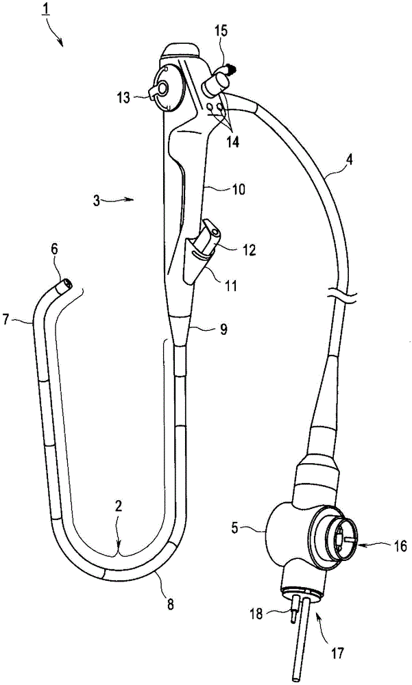
Electronic endoscope

An electronic endoscope and internal space technology, applied to endoscopes, telescopes, medical science and other directions, can solve the problems of obstructing the thin diameter of the insertion part and being useless, and achieve the effect of ensuring electromagnetic compatibility

Active Publication Date: 2015-07-29
OLYMPUS CORP
View PDF9 Cites 8 Cited by
  • Summary
  • Abstract
  • Description
  • Claims
  • Application Information

AI Technical Summary

Problems solved by technology

[0005] However, in conventional electronic endoscopes, since a signal cable bundle having a circular cross-section that binds a plurality of cables and bundles them into one is arranged in the insertion portion, there is a problem that a useless space is generated in the insertion portion and the narrowing of the insertion portion is hindered. The problem
[0006] Moreover, in the conventional electronic endoscope in which the insertion portion is provided with a bending portion, in order to prevent the signal cable bundle from being bent longitudinally by other built-in objects in the bending portion of the bending operation, it is necessary to set a distance from other built-in objects and Ensuring a sufficient space in the curved part hinders the narrow diameter of the insertion part.

Method used


Image

  • Electronic endoscope
  • Electronic endoscope
  • Electronic endoscope

Examples


no. 1 reference example

[0138] Here, a reference example related to the structure of the tip portion 6 will be described below. in addition, Figure 21 It is a perspective view showing the structure of the tip part, Figure 22 It is a front view showing the structure of the tip part, Figure 23 It is a side view showing the structure of the tip part, Figure 24 It is a side view of the distal end in a state where the treatment instrument is led out from the opening.

[0139] Such as Figure 21 and Figure 22 As shown, the distal end hard portion 20 of the distal end portion 6 of the endoscope 1 has a distal end surface 73 on which an observation window 71 and an illumination window 72 are arranged, and a protrusion extending toward the distal end side from which a tapered surface 74 is formed on the distal end surface 73. Section 75. In addition, an opening 21 communicating with the treatment instrument channel 48 is formed in the protruding portion 75 .

[0140] Such as Figure 23 As shown, ...

no. 2 reference example

[0143] Next, a reference example related to connection of cylindrical members disposed on the insertion portion 2 and the like will be described below. in addition, Figure 25 is a perspective view showing two cylindrical parts fitted and connected, Figure 26 It is a cross-sectional view of two cylindrical parts fitted, Figure 27 is along Figure 26 The cross-sectional view of the two cylindrical parts of the XXVII-XXVII line, Figure 28 It is a perspective view of two cylindrical parts showing the structure after obliquely cutting and connecting the end faces, Figure 29 It is a cross-sectional view of two cylindrical parts showing the structure after obliquely cutting and connecting the end faces, Figure 30 It is a perspective view of two cylindrical parts showing the structure after step-cutting and connecting the end faces, Figure 31 It is a cross-sectional view of two cylindrical members showing a structure after step-cutting and connecting end faces.

[0144] S...


PUM


Abstract

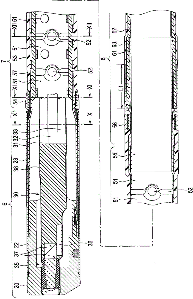
An electronic endoscope (1) is provided with the following: a plurality of metal cylinder members (51, 55, 59, 63) that are connected by electrical conduction so as to electromagnetically shield an internal space formed in an insertion part (2); a treatment tool channel (48) in which the center (O1) is disposed in any one quadrant of an orthogonal coordinate system with the origin thereof being the center (O) of the insertion part (2); and a plurality of small signal cables (31, 32, 33) that extend from an image pickup unit (30) and that have disposed therein, within at least a curved section (7), centers (O2, O3, O4) in quadrants that are different from the above any one quadrant and that are divided from that one quadrant at one axis (Y) of an orthogonal coordinate system which follows the curving vertical direction of the curved section (7). By being provided with the foregoing, the electronic endoscope can secure electromagnetic compatibility (EMC) and make the diameter of the insertion part smaller by efficiently disposing the plurality of cables so that the cables do not buckle within the curved part.

Description

technical field [0001] The present invention relates to an electronic endoscope provided with an imaging device at the distal end of an insertion portion. Background technique [0002] Conventionally, there is an electronic endoscope having an imaging device for forming an observation image of a subject focused by an objective optical system provided at a distal end of an insertion part and camera. [0003] In such a conventional electronic endoscope, for example, as disclosed in JP-A-2006-55531, a signal cable harness as an imaging cable for transmitting power and drive signals to an imaging device passes through the main body, the composite body, and the insertion portion from the insertion portion. Cables and the like are arranged to an endoscope connector connected to external devices such as a video processor. [0004] A plurality of signal system cables and power supply cables provided in such conventional electronic endoscopes are arranged as one signal cable bundle...

Claims


Application Information

Patent Timeline
Patent Type & Authority Applications(China)
IPC IPC(8): A61B1/04G02B23/24
CPCA61B1/0011G02B23/2476A61B1/00114A61B1/00071A61B1/05A61B1/018A61B1/00096A61B1/07A61B1/009
Inventor 松田英二籏野庆佑
Owner OLYMPUS CORP
Why Eureka
Try Eureka