Dental implant

A technology for implants and dentistry, applied in dental prosthesis, dentistry, dental implants, etc., can solve problems such as weak bonding, plaque and tartar deposits, and difficulty in removing screw parts 5, so as to reduce the risk of fracture and prevent gap penetration , Prevention of inflammation and peri-implant mucositis

Inactive Publication Date: 2015-07-29
大恩土主
View PDF10 Cites 4 Cited by
  • Summary
  • Abstract
  • Description
  • Claims
  • Application Information

AI Technical Summary

Problems solved by technology

[0006] The feature of the above structure is to provide a supply channel that can supply human growth factors in the bone structure around the root of the tooth, but its structure is complex, the bonding force between the crown 50 and the root 3 is weak, and there is a gap between the middle column 18 of the abutment. There is a risk of the screw combination of the crown 50 and the root 3 being unraveled
[0007] However, in the above-mentioned structure, the screw portion 5 is integrally formed on the upper setting platform 2, and there is still a risk of breaking the upper setting platform 2 formed with the screw portion 5. Moreover, when the upper setting platform 2 is broken, it is difficult to remove the broken screw portion 5.
[0008] In addition, the above-mentioned screw part 5 is screwed only on the inner side of the artificial tooth fixture 11, so the bonding force between the artificial tooth fixture 11 and the upper setting platform 2 and the lower setting platform 6 is weak due to the small surface area of ​​the screwed part. There is a risk that the screw joint may be unraveled
[0009] In addition, since the structure of the prior art described above is a structure in which the crown 50 is connected to the root 3 as a whole when there is no surface in contact with the gingival part of the abutment, it is only possible to In addition, there is also the problem that a large amount of plaque and tartar are easily deposited on the gum line 62

Method used


Image

  • Dental implant
  • Dental implant
  • Dental implant

Examples


Embodiment Construction

[0056] Hereinafter, preferred embodiments of the dental implant according to the present invention will be described in detail with reference to the accompanying drawings.

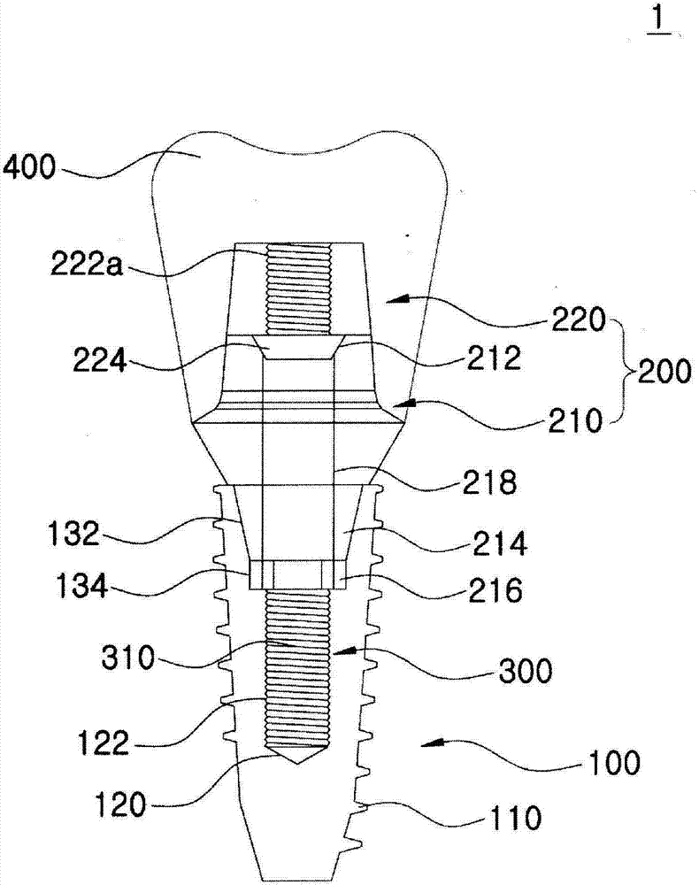
[0057] image 3 It is a schematic cross-sectional view of an embodiment of the dental implant according to the present invention, Figure 4 for image 3 The exploded cross-sectional schematic diagram of the present invention shown, Figure 5 (a), 5(b), 5(c) are image 3 Shown is an exploded cross-sectional schematic view of an embodiment of the abutment of the present invention, Figure 6 (a), 6(b), 6(c) are image 3 The schematic diagram of the embodiment of screw post among the present invention shown, Figure 7 It is a combined cross-sectional schematic view of the second embodiment of the dental implant according to the present invention, Figure 8 It is a combined cross-sectional schematic view of the third embodiment of the dental implant according to the present invention, Figure 9 is an exp...


PUM


Abstract

The present invention relates to a dental implant, and more particularly, to a dental implant in which a fixture and an abutment are together by a separate screw post so as to prevent the breakage of an implant screw tightening part and uniformly transmit forces over the entirety of a contact surface, to thereby prevent stresses from being partially concentrated, and in which the screw-tightening direction between the fixture and the abutment is variable so as to improve the coupling force between the fixture and the abutment and fundamentally prevent a screw from becoming loosened. The dental implant of the present invention comprises said fixture and abutment, the abutment including a lower abutment to be fitted onto the fixture, and an upper abutment connected to an upper portion of the lower abutment, the lower abutment and the upper abutment being separate from each other. The upper abutment and the fixture are coupled and fixed by the screw post.

Description

technical field [0001] The present invention relates to a dental implant, in particular to a method of combining a retaining screw and an abutment by using a separate screw column, thereby preventing the screw joint of the implant from being broken, and at the same time transmitting force uniformly to the entire contact surface, preventing stress on the part The phenomenon of concentration, moreover, make the direction of the screw combination between the retaining nail and the abutment reverse, improve the bonding force between the retaining nail and the abutment, and fundamentally solve the problem of the dental implant with the screw untwisted. Background technique [0002] Generally speaking, an implant refers to an artificial substitute that can reproduce the same shape and function as a natural tooth, and its structure is as follows: figure 1 As shown, it includes: a titanium fixture (fixture) 10, the outer peripheral surface of which forms a thread 11 to be set on the...

Claims


Application Information

Patent Timeline
Patent Type & Authority Applications(China)
IPC IPC(8): A61C8/00A61C13/263
CPCA61C8/0037A61C8/0048A61C8/0068A61C8/00A61C8/0069A61C8/006A61C8/0045A61C8/0063
Inventor 崔昊埈
Owner 大恩土主
Why Eureka
Try Eureka