Image processing apparatus using differential camera
An image processing and differential image technology, applied in the field of rapid detection of marks, can solve the problem of mistaking objects for mouse cursor icons, etc., and achieve the effect of reducing the burden of the CPU and reducing power consumption
- Summary
- Abstract
- Description
- Claims
- Application Information
AI Technical Summary
Problems solved by technology
Method used
Image

Examples
Embodiment 1
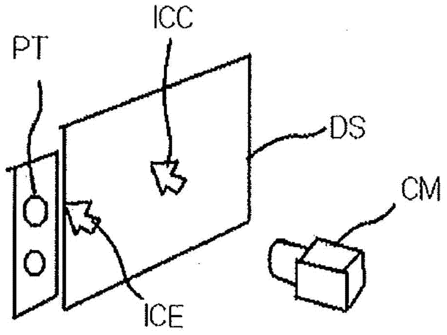
[0014] Recently, a technique of capturing by a camera and recognizing the pointing of a mouse cursor icon in a monitor from the captured image has been developed. For example, there is a technology of Korean Patent No. 10-0936816 titled "Pointing device using camera and outputting mark". The technique was invented by the inventors of the present invention. The pointing technique above includes an embodiment of an image processing system that identifies markers from odd frames, where a monitor displays marker images in odd frames and normal images in even frames. Such as figure 1 As shown, the marker is easy to detect if it is a mouse cursor icon ICC located at the central area of the monitor and there is a sufficiently clear border around the marker. However, if the mouse cursor icon ICE is touching figure 1 If there is an object whose texture PT is similar to that of the mouse cursor icon, it may be difficult for the image processing system to distinguish the mouse curso...
Embodiment 2
[0040] This embodiment is a modification of Embodiment 1. Embodiment 1 relates to an image processing system that computes a differential image between two sequentially captured images, where the first image is a black blank image (the blank image is all pixel values same image) and the marked image, and the second image is a modified normal image, where the modification means that the brightness of the area corresponding to the marked is reduced.
[0041] In comparison, this example:
[0042] sequentially displaying a first image and a second image, wherein the first image is a composite of a first color (eg, red) component image of a marker (eg, a white marker) and a complementary color component image of the first color of a normal image, and
[0043] The second image is a composite of the complementary color component image of the first color of the marker and the first color component image of the normal image.
[0044] For a given full-color image, a first color (eg, r...
Embodiment 3
[0046] This embodiment is a modification of Embodiment 1. Embodiment 1 relates to an image processing system that computes a differential image between two sequentially captured images, where the first image is a black blank image (the blank image is all pixel values same image) and the marked image, and the second image is a modified normal image, where the modification means that the brightness of the area corresponding to the marked is reduced. In contrast, this embodiment sequentially displays a black blank image followed by a normal image instead of displaying a modified normal image, where the modification means that the brightness of the area corresponding to the mark is reduced. (The order of display can be changed. That is, a dark blank image can be displayed after a normal image is displayed.) In other words, this embodiment relates to an image processing system that alternately and rapidly displays three kinds of images (marker images , blank image, and normal imag...
PUM
 Abstract
Description
Claims
Application Information
 - R&D
- Intellectual Property
- Life Sciences
- Materials
- Tech Scout
- Unparalleled Data Quality
- Higher Quality Content
- 60% Fewer Hallucinations
Browse by: Latest US Patents, China's latest patents, Technical Efficacy Thesaurus, Application Domain, Technology Topic, Popular Technical Reports.
© 2025 PatSnap. All rights reserved.Legal|Privacy policy|Modern Slavery Act Transparency Statement|Sitemap|About US| Contact US: help@patsnap.com