Casting area moving type dust removing device for continuous casting machine

A mobile dust removal and continuous casting machine technology, which is applied to casting equipment, dust removal, metal processing equipment, etc., can solve problems affecting the quality of billets, rapid drop of molten steel temperature, pollution of the environment, etc., to achieve good dust removal effect and reasonable layout , the effect of convenient operation

Active Publication Date: 2015-08-05
BEIJING SHOUGANG INT ENG TECH
View PDF13 Cites 15 Cited by
  • Summary
  • Abstract
  • Description
  • Claims
  • Application Information

AI Technical Summary

Problems solved by technology

However, hot flue gas is generated instantaneously and rises rapidly during casting. If there is not a large enough flue gas collection space and guide it to the side suction port, it will be difficult to remove dust and only a small amount of flue gas can be discharged.
The effect of continuing to increase the air suction is not obvious, and it will cause the temperature of the molten steel in the tundish to drop too quickly, which will affect the quality of the slab
The dust removal effect of such dust removal facilities is very poor, which cannot effectively protect the health of workers, and also pollutes the environment

Method used


Image

  • Casting area moving type dust removing device for continuous casting machine
  • Casting area moving type dust removing device for continuous casting machine

Examples


Embodiment Construction

[0016] In order to enable those skilled in the art to better understand the present invention, the present invention will be further described in detail below in conjunction with the accompanying drawings and specific embodiments.

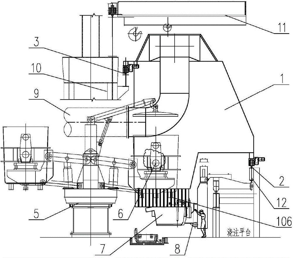
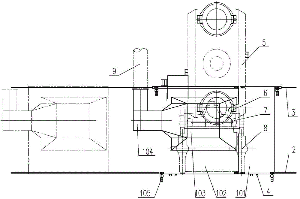
[0017] In this specific embodiment, the mobile dust removal facility in the casting area of ​​the continuous casting machine is composed of a dust collection cover 1 , a low rail 2 and a high rail 3 . like figure 1 and figure 2 As shown, the cover body of the dust collection hood 1 spans the steel ladle and the tundish longitudinally, making full use of the limited height space between the bottom of the beam of the crown block 11 and the top of the ladle turret 5 to form a dust collection space, so as to facilitate the collection of rising and diffusing smoke. Gas; the horizontal letter includes the ladle turntable 5 and the tundish car 8, meeting the high / low rotation requirements of the ladle on the turntable 5.

[0018] Because of its large c...


PUM


Abstract

A casting area moving type dust removing device for a continuous casting machine belongs to the technical field of steel-making continuous casting. The casting area moving type dust removing device for the continuous casting machine comprises a dust collecting cover, moving rails, and a workshop dust removing system. The moving rails comprise high rails and low rails which are arranged in parallel. The dust collecting cover consists of two independent cover bodies including a main dust collecting cover and an auxiliary dust collecting cover that are arranged on bilateral sides of a casting site steel ladle rotary table. Each cover body is independently supported on the low rails and the high rails by its own wheels, and the cover body can move linearly along the rails. Adjacent sides of the two cover bodies are open without a sealing wall. A flow guidance cone and a dust removing pipeline moving along with it are arranged on the top of the main dust collecting cover. The main dust collecting cover and the auxiliary dust collecting cover move to the casting site upon casting; the cover bodies cover above the entire casting area, thereby forming a relatively complete dust removing space. The dust removing pipeline belonging to the main dust removing cover is communicated with the workshop dust removing system. The workshop dust removing system finishes the fume purification and discharges the purified fume. The casting area moving type dust removing device for the continuous casting machine has the advantages that the dust removing space covers the steel ladle and the intermediate ladle, thereby the quickly ascending fume and dust can be collected as much as possible; and accordingly the dust removing effect is good; the equipment layout is reasonable; the structure is simple; and the operation is convenient.

Description

technical field [0001] The invention belongs to the technical field of steelmaking and continuous casting, and in particular relates to a mobile dust removal device in the casting area of ​​a continuous casting machine, which covers the casting area of ​​the continuous casting machine. Background technique [0002] Continuous casting is the main means of forming iron and steel materials at present. The molten steel that has undergone primary or secondary smelting is gradually solidified from a liquid state into a desired solid shape (slab, square billet, round billet, special-shaped billet, etc.) through the continuous casting machine. . [0003] During the pouring process of the continuous casting machine, the hot liquid steel falls from the ladle into the tundish, and then from the tundish into the crystallizer for pouring. During this process, a large amount of smoke and dust gas will be generated, especially when the molten steel falls from the ladle into the tundish. T...

Claims


Application Information

Patent Timeline
Patent Type & Authority Applications(China)
IPC IPC(8): B08B15/00B22D45/00
CPCB08B15/02B22D45/005
Inventor 宫江容唐落谦刘彭涛方颖张爱刚万贵义
Owner BEIJING SHOUGANG INT ENG TECH
Why Eureka
Try Eureka