Hybrid power system

A technology of hybrid power system and clutch transmission, applied in the field of vehicle transmission system, can solve the problems that the engine cannot participate or be driven independently, reduce the overall efficiency of the hybrid power system, limit the use range of the whole vehicle, etc., and achieve shortened radial layout space, The effect of improving the range of use and enriching the axial space

Inactive Publication Date: 2015-08-05
安徽易佳斯动力科技有限公司
View PDF6 Cites 4 Cited by
  • Summary
  • Abstract
  • Description
  • Claims
  • Application Information

AI Technical Summary

Problems solved by technology

[0004] Due to the high cost of batteries, large volume and weight, it is impossible to install too many batteries for hybrid vehicles, so the engine must participate in driving to a large extent, and in current solutions, the engine cannot participate or be independent Drive the whole vehicle to reverse, which limits the range of use of the whole vehicle, and the engine participates in the drive, especially under the condition of independent drive, there are fewer gears. Since the efficiency of the engine is far lower than that of the motor, the overall efficiency of the hybrid system is reduced.

Method used


Image

  • Hybrid power system
  • Hybrid power system
  • Hybrid power system

Examples


Embodiment 1

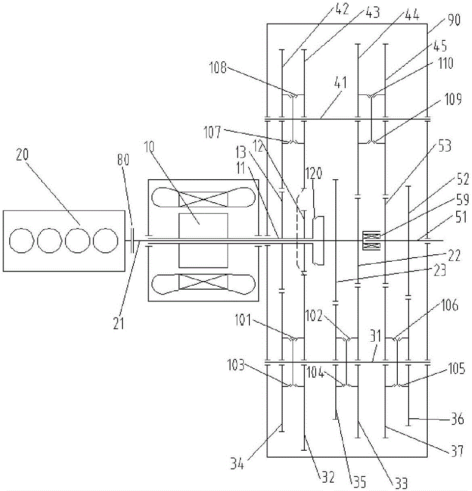
[0031] Such as figure 1 As shown, a hybrid power system includes a first drive motor 10, an engine 20, a clutch 80, and a transmission device.

[0032] The speed change device includes a gearbox body 90 and a first input shaft 11 located in the gearbox body, a first clutch transmission unit corresponding to the first input shaft and a third clutch transmission unit, a second input shaft 21, and a second input shaft 21 corresponding to the first input shaft. A second clutch transmission unit and a fourth clutch transmission unit of the shaft, an intermediate shaft 31, a fifth clutch transmission unit corresponding to the intermediate shaft, a sixth clutch transmission unit, a reverse gear shaft 41, a first clutch transmission unit corresponding to the reverse gear shaft Seven clutch transmission units, an eighth clutch transmission unit, a ninth clutch transmission unit, a tenth clutch transmission unit and an output shaft 51 .

[0033] The first clutch transmission unit inclu...

Embodiment 2

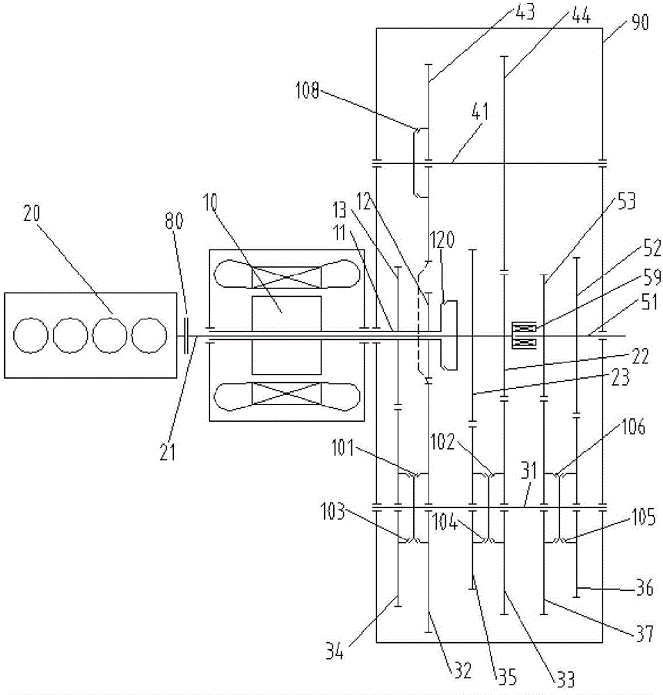
[0184] Such as figure 2 As shown, this embodiment 2 includes some technical features in embodiment 1, the difference is that the seventh clutch transmission unit and the ninth clutch transmission unit are canceled for the corresponding reverse gear shaft, and the tenth clutch transmission unit connects with the reverse gear shaft through one The driven gear that is fixedly connected and meshed with the fifth driven gear 52 or the sixth driven gear 53 is replaced (the tenth driven gear 44) to realize the power connection between the second input shaft and the reverse shaft. The scheme eliminates the possibility of establishing a power connection between the reverse gear shaft 41 and the output shaft 51, and switches the power of the intermediate shaft from the fifth clutch transmission unit to the output shaft 51 to the sixth clutch transmission unit to the output shaft. 51 There will be power interruption during the process of outputting power. Compared with the technical sol...

Embodiment 3

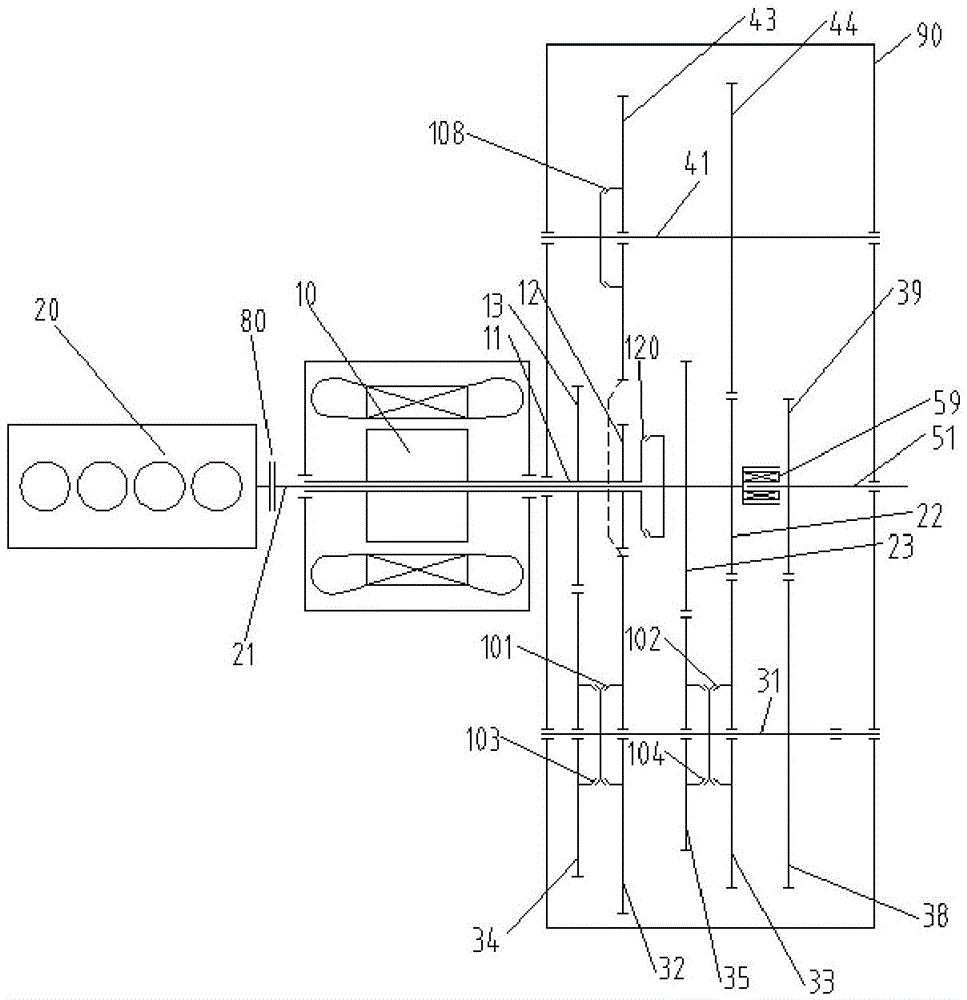
[0186] Such as image 3As shown, the third embodiment includes some technical features of the first embodiment, the difference is that the fifth and sixth clutch transmission units are omitted, and the intermediate shaft 31 is driven to the output shaft 51 through gear meshing. During specific implementation, an intermediate gear 38 is coaxially fixed on the intermediate shaft 31, an output gear 39 is coaxially fixed on the output shaft 51, and the intermediate gear meshes with the output gear. Compared with the technical solution of the embodiment 2, the advantage of the embodiment 3 is that two clutch transmission units can be reduced, which reduces the cost of the hybrid power system, and the disadvantage is that the gears are reduced. Compared with the prior art, this embodiment 2 increases the reverse gear of the engine, so that the engine can participate in or independently drive the whole vehicle to reverse, which greatly improves the range of use of the whole vehicle. ...


PUM


Abstract

The invention discloses a hybrid power system. The hybrid power system comprises a first driving motor, an engine, a clutch and a speed change device; the speed change device comprises a gear box body, a first input shaft, a first clutch transmission unit, a third clutch transmission unit, a second input shaft, a second clutch transmission unit, a fourth clutch transmission unit, an intermediate shaft, a fifth clutch transmission unit, a sixth clutch transmission unit, a gear reversing shaft, a seventh clutch transmission unit, an eighth clutch transmission unit, a ninth clutch transmission unit and an output shaft; the first input shaft is arranged in the gear box body; the first clutch transmission unit and the third clutch transmission unit are corresponding to the first input shaft; the second clutch transmission unit and the fourth clutch transmission unit are corresponding to the second input shaft; the fifth clutch transmission unit and the sixth clutch transmission unit are corresponding to the intermediate shaft; the seventh clutch transmission unit, the eighth clutch transmission unit and the ninth clutch transmission unit are corresponding to the gear reversing shaft. According to the hybrid power system, the longitudinal arrangement of the power system can be implemented, gears under the driving conditions are greatly increased, the engine can participate in vehicle reversing or can be used for independently driving the vehicle reversing, and accordingly the possibility of the operation of the engine in the high efficiency area is greatly improved and the application rage of a vehicle is greatly extended.

Description

technical field [0001] The invention relates to vehicle transmission system technology, in particular to a hybrid power system. Background technique [0002] Due to the advantages of zero emissions, pure electric vehicles are of great significance to improving global air quality, but limited by the level of battery technology, high manufacturing cost, small capacity, and long charging time, the application of pure electric vehicles is greatly restricted. [0003] For the problems existing in pure electric vehicles, the current general solution is to use the engine system and the motor system at the same time. According to the relationship between the engine system and the motor system, it is divided into a parallel hybrid system and a series power system. In the parallel hybrid system, the engine system and the electric motor system are connected in parallel, and both the engine system and the electric motor system can directly output power to the vehicle. In a series elect...

Claims


Application Information

Patent Timeline
Patent Type & Authority Applications(China)
IPC IPC(8): B60K6/36B60K6/44B60K6/547
CPCY02T10/62
Inventor 何祥延袁一卿张寅伍国强
Owner 安徽易佳斯动力科技有限公司
Why Eureka
Try Eureka