Material bin discharging device

A technology of discharging device and silo, which is applied in the direction of transmission, packaging, loading/unloading, etc., can solve the problems of affecting the discharge effect of the silo, increasing the resistance of the propulsion movement of the screw propulsion device, wasting energy consumption, etc., and achieving high The effect of discharging efficiency, reducing the opening density and smooth discharging effect

Inactive Publication Date: 2015-08-05
车战斌
View PDF0 Cites 0 Cited by
  • Summary
  • Abstract
  • Description
  • Claims
  • Application Information

AI Technical Summary

Problems solved by technology

[0005] Second, in the above-mentioned structure, although the arrangement is relatively dense, there will still be some materials remaining between the two screw propulsion devices. These remaining materials cannot be discharged for a long time, and will form serious arching under the action of continuous extrusion. , and form an extremely rough arched surface between the screw propulsion devices, the screw propulsion device located in between has to carry out the propulsion and export movement of materials in the channel formed by the rough arch surface, so that the materials entering the screw propulsion device or between them are more accurate It is easy to arch, which increases the resistance of the propulsion movement of the screw propulsion device, wastes energy consumption, and affects the discharge effect of the silo

Method used


Image

  • Material bin discharging device
  • Material bin discharging device
  • Material bin discharging device

Examples


Embodiment Construction

[0050] The details of the present invention can be understood more clearly with reference to the accompanying drawings and the description of specific embodiments of the present invention. However, the specific embodiments of the present invention described here are only for the purpose of explaining the present invention, and should not be construed as limiting the present invention in any way. Under the teaching of the present invention, the skilled person can conceive any possible modification based on the present invention, and these should be regarded as belonging to the scope of the present invention.

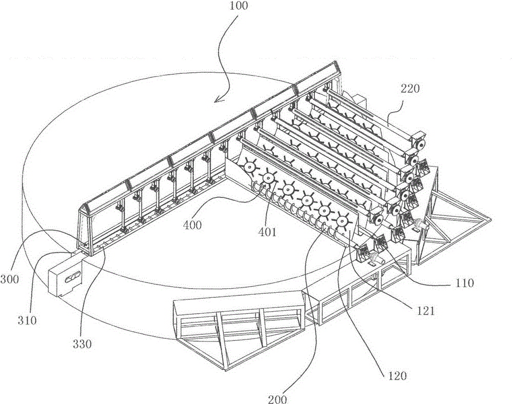
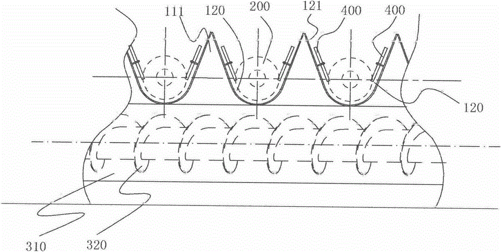
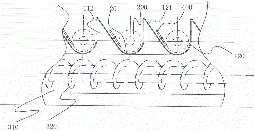
[0051] figure 1 An embodiment of the silo discharge device according to the invention is shown. Such as figure 1 As shown, the silo discharge device of the present invention is at least arranged with strip-shaped protrusions 110 at intervals on the surface of the bottom 100 of the silo, and a spiral groove 120 formed between every two adjacent protrusions 110 is arrange...


PUM


Abstract

A material-discharging apparatus of a material chamber. Strip-shaped protrusions (110) are arranged at intervals on the surface of the bottom (100) of the material chamber. Screw conveyor material-guiding mechanisms (200) are arranged in material-guiding grooves (120) formed between every two adjacent protrusions (110). The material-guiding grooves (120) are in communication with a material-discharging channel (310) accommodating a material-discharging mechanism (300). Rotary arch-breaking wheels (400) are arranged along sidewalls (121) of at least one side of the material-guiding grooves (120). The arch-breaking wheels (400) are rotatively supported on the sidewalls (121) of the strip-shaped protrusions (110). Paddling structures (401) are radially arranged on the peripheries of the rotary arch-breaking wheels (400). The paddling structures (401) are interference installed with moving parts (200) of the material-discharging apparatus. When moving, the moving parts (200) drive the arch-breaking wheels (400) into rotation for arch breaking. The material-discharging apparatus of the material chamber improves the fluidity of materials on the wall surface of the material chamber, thus preventing formation of arches on the wall surface structure of material chamber.

Description

technical field [0001] The invention relates to a bin discharging device for storing loose materials. Background technique [0002] The lower part of the existing silo is generally in a shrinking shape, and a discharge port or a discharge channel is set on the narrowed bottom surface to provide a gathering effect like a funnel. The arch is completely dependent on the contracted silo bottom structure at the bottom of the silo and it is difficult to export it from the discharge port. For this reason, people have proposed a kind of feed bin, as the utility model patent of publication number 202897570U. In this patent, the two sides of the bottom of the silo are tapered to form more than one longitudinal discharge channel, and an auger is longitudinally arranged at the bottom of the discharge channel. When the material falls to the bottom of the silo along the cone surface, the material falling into the bottom of the silo is output from the silo by the forced propulsion of the...

Claims


Application Information

Patent Timeline
Patent Type & Authority Applications(China)
IPC IPC(8): B65G65/46B65D88/68
CPCB65D88/68F16H7/00B65G65/46B65G2201/04B65G2207/40
Inventor 车战斌
Owner 车战斌
Why Eureka
Try Eureka