Magnetic push electromechanical mixed antitheft alarm lock

An anti-theft alarm and magnetic push technology, applied in the field of anti-theft locks, can solve the problem of not using anti-theft locks, etc.

Inactive Publication Date: 2015-08-05
余登会
6 Cites 0 Cited by

AI-Extracted Technical Summary

Problems solved by technology

[0002] There are many kinds of anti-theft locks in use now, but basically the key is used to open the marble and then rotate to drive the deadbolt to open the anti-theft lock. There is no anti-theft lock that can combine electromechanical interlocki...

Abstract

The invention discloses a magnetic push electromechanical mixed antitheft alarm lock; a back lock cylinder thereof is totally separated from a connecting body and a front lock cylinder; the connecting body is hidden in an invisible hole; a locking end of a rotating block and a lock column are hidden in the front lock cylinder and a lock body for locking the front lock cylinder; a magnetic push lock and an attractive lock are hidden in the lock body and the back lock cylinder for locking the back lock cylinder; the front and back lock cylinders asynchronously rotate to alarm; an electronic remote control device is mounted in a power supply circuit of an electromagnet to interrupt the power supply circuit of the electromagnet, and a safety lock cross cannot be opened to achieve a thorough antitheft effect; and the electromechanical interlocking, the mechanical interlocking, the invisibility, the connecting invisibility of the front and back lock cylinders and the asynchronous alarming are integrated as a whole, so that thieves cannot open the interlocking device and rotate the back lock cylinder, and only can rotate the front lock cylinder without rotating the back lock cylinder even if a side locking device and a cross locking device are damaged by a barbaric method.

Application Domain

Non-mechanical controlsKeys +1

Technology Topic

EngineeringInvisibility +3

Image

  • Magnetic push electromechanical mixed antitheft alarm lock
  • Magnetic push electromechanical mixed antitheft alarm lock
  • Magnetic push electromechanical mixed antitheft alarm lock

Examples

  • Experimental program(1)

Example Embodiment

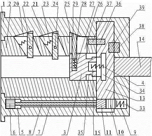
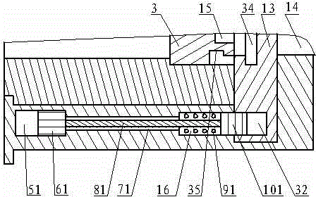
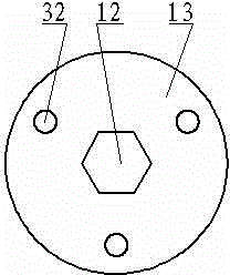
[0076] The magnetic push electromechanical hybrid anti-theft alarm lock of the present invention has a magnetic locking device, an oblique lock device, a horizontal lock device, a synchronous connection system, with or without an electric insurance anti-theft system, with or without an asynchronous alarm system, and a locking system without a pin lock But it can cooperate with the locking system of the pin lock to become a better and safer anti-theft lock; mainly includes: lock body 1, front lock core 2, rear lock core 13, connecting body 3, return spring 4, connecting hole 12 , Connecting tongue 14, spring bearing hole 15, special key hole, special key, magnetic push hole 5, push magnet 6, slide push hole 7, push rod 8, lock hole 32, top post 11, push lock head 10. Magnetic push spring 9, magnetic attraction hole 51, pull magnet 61, slide pull hole 71, spring hole 16, magnetic attraction spring 91, pull lock head 101, lock bearing hole 33, inclined slot 21, inclined lock slot 20 , Rotating block 22, rotating pin, top spring 23, horizontal hole 26, longitudinal lock slot 25, telescopic hole 27, lock column 29, push spring 28, main contact 36, sub contact 37, fixed contact 38, rotating contact Point 39, electric insurance anti-theft system, asynchronous alarm system;
[0077] The said magnetic push electromechanical hybrid anti-theft alarm lock without the anti-theft lock of the electric insurance anti-theft system and asynchronous alarm system becomes a magnetic push mechanical anti-theft lock. The said magnetic push mechanical anti-theft lock has a magnetic locking device, Oblique lock device, horizontal lock device, synchronous connection system, there is no locking system of the pin lock, but it can cooperate with the locking system of the pin lock to become a better and safer anti-theft lock; mainly includes: lock body 1, front lock core 2. Rear lock cylinder 13, connecting body 3, return spring 4, spring bearing hole 15, connecting hole 12, connecting tongue 14, special key hole, special key, magnetic push hole 5, push magnet 6, slide push hole 7. Push rod 8, lock hole 32, top post 11, deep lock bearing hole 33, push lock head 10, magnetic push spring 9, magnetic suction hole 51, pull magnet 61, sliding hole 71, spring hole 16 , Magnetic spring 91, shallow lock bearing hole 33, pull lock head 101, chute 21, slanted lock groove 20, turn block 22, pivot pin, top spring 23, horizontal hole 26, longitudinal lock groove 25, telescopic hole 27. Lock column 29. Push spring 28.
[0078] The lock body 1 has a rear lock core 13 movably installed at the rear end of the front lock core 2 and is completely disconnected from the front lock core 2. The rear end of the rear lock core 13 is fixed with a connecting tongue 14 through which the connecting tongue 14 penetrates After passing through the through hole at the rear of the lock body 1, it is connected with the linkage mechanism, and the linkage mechanism is connected with the lock tongue; the lock body 1 has a sliding hole, a magnetic hole, a spring hole 16, an oblique lock slot 20 and a longitudinal lock slot 25 The front lock core 2 has a magnetic hole, a sliding hole, a spring hole 16, a chute 21, a horizontal hole 26, a special key hole and an invisible hole; the synchronous connection system includes an invisible hole, a connecting hole 12 And the connecting body 3, the connecting body 3 is installed in the invisible hole. The magnetic locking device includes magnetic push locking and attraction locking. The push locking is installed in the magnetic pushing channel composed of the magnetic pushing hole 5, the sliding pushing hole 7, the locking hole 32 and the locking bearing hole 33. The lock is installed in the suction channel composed of the magnetic suction hole 51, the sliding hole 71, the spring hole 16 and the locking hole 32. A rotating block 22, a rotating pin and a top spring 23 are installed in the chute 21, and a slant lock device composed of the rotating block 22, the rotating pin and the top spring 23 and the chute 21 and the slant lock slot 20 is installed. A push spring 28 and a lock column 29 are installed in the telescopic hole 27. The push spring 28 is installed at the bottom of the telescopic hole 27, and the lock column 29 passes through the front end of the telescopic hole 27 in front of the push spring 28. The fixed contact 38 and the rotating contact 39 and the electronic remote control device are connected to the power supply circuit of the electromagnet, the power supply circuit is connected to the power supply, and the iron core of the electromagnet is horizontally connected with the safety lock to form an electric insurance anti-theft system; The said asynchronous electromechanical hybrid magnetic anti-theft alarm lock has or does not. The main contact 36 and the auxiliary contact 37, the relay and the alarm are connected to the power supply circuit of the asynchronous alarm system, and the power supply circuit of the asynchronous alarm system is connected to the power supply; the asynchronous alarm system is provided in the asynchronous electromechanical hybrid magnetic anti-theft alarm lock Or not.
[0079] The lock body 1 has a lock core hole and a via hole at the center, and the via hole is a hole used to allow the connecting tongue 14 to pass through at the rear end of the lock body 1; the lock core hole It is a round hole. In front of the through hole, it is divided into front lock cylinder 2 holes and rear lock cylinder 13 holes. The diameter of the rear lock cylinder 13 holes is larger than that between the front lock cylinder 2 holes, and the front lock cylinder 2 holes are in the rear lock. In front of the core 13 hole; the front lock core 2 is installed in the front lock core 2 and the rear lock core 13 is installed in the rear lock core 13, and the front lock core 2 is installed in front of the rear lock core 13, and the rear lock The rotation diameter of the core 13 is larger than the rotation diameter of the front key cylinder 2. There is a lock bearing hole 33 on the lock body 1 at the rear end of the rear lock cylinder 13 hole outside the through hole, and a magnetic lock bearing hole 33 is provided on the lock body 1 outside the front lock cylinder 2 hole. Moving holes, sliding holes, or, on the lock body 1 outside of the front lock cylinder 2 holes, there are magnetic moving holes, sliding holes and spring holes 16 communicating with the locking bearing hole 33. The lock bearing hole 33 is the bearing hole at the rear end of the rear lock core 13 hole outside the through hole that is larger than the hole diameter of the front lock core 2 hole, and the lock hole 32 on the rear lock core 13 The positions are corresponding and communicated, and a magnetic push spring 9 and a push locking head 10 are installed in the locking bearing hole 33. The magnetic hole includes a magnetic push hole 5 and a magnetic suction hole 51. The front end of the lock body 1 outside the front lock core 2 hole, but does not penetrate the front end of the lock body 1, penetrates the sliding hole, and the magnetic push The hole 5 is used for installing the pushing magnet 6 and allowing the pushing magnet 6 to slide in the magnetic hole, and the magnetic attraction hole 51 is used for installing the pulling magnet 61 and allowing the pulling magnet 61 to slide in the magnetic hole. The sliding hole includes a sliding push hole 7 and a sliding pull hole 71. The lock body 1 behind the magnetic hole outside the front lock core 2 penetrates the magnetic hole and the locking hole 32, or is in the front lock core 2. The lock body 1 behind the magnetic hole outside the hole penetrates the magnetic hole and the spring hole 16. The sliding push hole 7 is used to install the sliding push rod and allow the sliding push rod to slide in the sliding push hole 7. The sliding hole 71 Used for installing the sliding rod and allowing the sliding rod to slide in the sliding hole 71. The spring hole 16 penetrates through the lock body 1 behind the sliding hole 71 outside the front lock cylinder 2 hole. The front end of the rear lock cylinder 13 hole whose diameter is larger than that of the front lock cylinder 2 hole, and the sliding hole 71 and the locking hole 32 pass through and are used to install the magnetic spring 91 and allow the magnetic spring 91 to slide elastically in the spring hole 16 and allow the sliding rod to pass through the middle of the magnetic spring 91. In order to facilitate assembly, the sliding hole and the magnetic hole can also become a continuous integral straight hole, but the position of the magnetic hole in the straight hole needs to be processed with a circlip position, which is used to install the circlip to fix Pull the installation position of the magnet 61 or limit the movement distance of the push magnet 6; the spring hole 16 can also form a continuous integral straight hole with the sliding hole 71 and the magnetic hole, but the circlip position must be processed in the straight hole , The circlip position is used to install the circlip to fix the magnetic spring 91. There are oblique lock grooves 20 and longitudinal lock grooves 25 in the round hole portion of the front lock cylinder 2 hole; the oblique lock grooves 20 are recessed and are longitudinal grooves along the direction of the lock cylinder hole. The position of the chute 21 on the front lock cylinder 2 corresponds to the position of the chute 21, which is used to allow the locking end of the rotating block 22 to move inside and lock the front lock cylinder 2 to rotate; the longitudinal lock groove 25 is recessed along the lock cylinder The longitudinal groove in the direction of the hole, the groove of the longitudinal groove is curved or inclined, and the longitudinal lock groove 25 on the front lock cylinder 2 hole corresponds to the position of the horizontal hole 26 on the front lock cylinder 2 for the lock cylinder 29 moves inside and locks the front lock cylinder 2 to rotate.
[0080] The front lock cylinder 2 has a special key hole, a concealed hole, a chute 21 and a horizontal hole 26, and a main contact 36 is fixed at the rear end of the front lock cylinder 2; The holes are all in the center of the rotation of the front lock core 2 or close to the center of rotation. Special key holes are provided in front of the invisible hole; the connecting body 3 is installed in the invisible hole, and the rear end of the connecting body 3 has a spring bearing hole 15. A return spring 4 is installed in the spring bearing hole 15. The chute 21 penetrates the outer surface of the front lock cylinder 2 and the special key hole on the lock cylinder of the special key hole part of the front lock cylinder 2, and is communicated with the oblique lock groove 20 and the special key hole, and Corresponding to the oblique lock groove 20 on the lock core hole, the rotating block 22, the rotating pin and the top spring 23 of the oblique lock device are used to install the rotating block 22, the rotating pin and the top spring 23 in the chute 21. The horizontal hole 26 penetrates the outer circular surface and the invisible hole of the invisible hole portion of the front lock cylinder 2, and communicates with the longitudinal lock groove 25 and the invisible hole, and is connected to the invisible hole on the lock cylinder hole. The longitudinal lock slot 25 corresponds to the lock cylinder 29 and the lock cylinder 29 moves in the horizontal hole 26.
[0081] The rear lock cylinder 13 is fixed with a rotating contact 39 and a main contact 36. The main contact 36 is at the front end of the rear lock cylinder 13, and the rotating contact 39 is fixed on the back of the rear lock cylinder 13 or on the cylindrical surface. Alternatively, the rotating contact 39 is fixed on the connecting tongue 14; the center of the rear end of the rear lock core 13 is fixed with the connecting tongue 14 passing through the through hole behind the lock body 1, and the front end of the rotation center of the rear lock core 13 has The connecting hole 12 has a locking hole 32 on the rear lock cylinder 13 on the outer side of the connecting hole 12 that is larger than the diameter of the front lock cylinder 2. The locking hole 32 is a bearing hole on the rear lock cylinder 13 or It is a through hole that penetrates the front and rear ends of the rear lock cylinder 13. The lock hole 32 in the magnetic push lock is a through hole, which corresponds to and communicates with the position of the sliding hole and the lock bearing hole 33. The locking hole 32 is a bearing hole or a through hole, corresponding to and communicating with the position of the spring hole 16. The connecting hole 12 is a bearing hole. The front end of the rotation center of the rear lock cylinder 13 penetrates the front end surface of the rear lock cylinder 13. The front part of the connecting hole 12 is the connecting port, and the hole surface of the connecting port is the connecting surface. There is a sliding groove 34 behind the connecting port; the hole surface of the connecting port is a polygonal hole or a hole with internal teeth or a hole with a keyway or a special-shaped hole composed of a circular arc surface and a flat surface. The shape of the connecting surface of the rear joint of the connecting body 3 is the same or similar, and the connection and fit of the connecting port and the rear joint are sliding connection and sliding fit, and the rear joint can enter the connecting hole 12 and slide in the connecting port; The groove 34 is a circular hole-shaped annular inner groove or a polygonal hole-shaped inner groove. The width of the sliding groove 34 is wider than the connecting surface of the rear joint. The rear joint completely enters the sliding groove 34 and does not connect to the connecting surface. Contact and be able to slide in the sliding groove 34.
[0082] The front part of the connecting body 3 is the front joint, and the rear joint has a rear joint. The outer diameter of the rear joint is smaller than the outer diameter of the front joint; there is an idle groove 35 between the front joint and the rear joint, and the outer diameter of the idle groove 35 is smaller than The outer diameter of the rear joint becomes a recessed groove; there is a spring bearing hole 15 in the middle of the rear end of the rear joint, and a return spring 4 is installed in the spring bearing hole 15; the return spring 4 is a coil spring that can Generate thrust; the shape of the front joint and the invisible hole are the same or similar, and the invisible hole is slidingly fitted; the connecting surface of the rear joint is a polygonal cylinder surface or a toothed cylinder or a keyed cylinder surface or A cylindrical surface composed of a circular arc surface and a plane, the shape of the rear joint is the same as or similar to the shape of the connecting port, and the connection and fit of the connecting surface of the rear joint and the hole surface of the connecting port are sliding connection and sliding fit; 35 is an annular outer groove or a polygonal outer groove. The width of the idler groove 35 is wider than the connecting surface of the connecting port at the front end of the connecting hole 12 on the rear lock cylinder 13, and the connecting surface of the connecting port completely enters the idler groove 35. It is in contact with the connecting surface of the rear joint and can slide in the idle groove 35.
[0083] The spring bearing hole 15 is a bearing hole for installing the return spring 4. There is or no spring bearing hole 15 at the bottom of the connecting hole 12; when there is no spring bearing hole 15 at the bottom of the connecting hole 12, the spring bearing hole 15 is provided in the connecting body 3. The back end of the spring bearing hole 15 is installed with a return spring 4, one end of the return spring 4 is pressed against the bottom of the connecting hole 12; when there is a spring bearing hole 15 at the bottom of the connecting hole 12, the spring bearing hole 15 is connected to The hole 12 is in the center part of the rotation of the rear lock core 13 or the part close to the center of rotation. The spring bearing hole 15 is the bearing hole at the bottom of the connecting hole 12. The spring bearing hole 15 is installed with the return spring 4 and the return spring 4 One end is pressed against the rear end of the rear joint of the connecting body 3.
[0084] The spring bearing hole 15 can also be at the bottom of the connecting hole 12 and the rear end of the rear joint of the connector at the same time. The spring bearing hole 15 at the bottom of the connecting hole 12 and the spring bearing hole 15 at the rear end of the rear joint can penetrate each other. The position spring 4 is installed in the spring bearing hole 15 with one end abutting in the spring bearing hole 15 at the bottom of the connecting hole 12 and the other end in the spring bearing hole 15 at the rear end of the rear joint.
[0085] The front end of the front connector of the connecting body 3 is matched with the front end of the push key 17. The push key 17 can push the front connector to slide in the invisible hole and drive the rear connector to slide in the connecting port of the connecting hole 12; 17 When pushing the front connector to slide in the invisible hole, the rear connector behind the front connector can be inserted into the connection port in the rear lock cylinder 13 to connect the front lock cylinder 2 and the rear lock cylinder 13, and the connection surface of the rear connector is connected to the connection port. Face fit; when the push key 17 with a special key is not used, and another object is inserted into the special key hole and then enters the invisible hole to push the front end of the connector 3, it is often mistaken that it can be connected by pushing it to the end, which causes the pushing distance to be too far. Long, the connecting surface of the rear joint enters the sliding groove 34, and the connecting surface of the connecting port enters the idle groove 35, so that the connecting surface of the connecting body 3 and the connecting hole 12 cannot contact and rotates idly.
[0086] The magnetic locking device includes magnetic push locking and attraction locking. The push magnet 6 of the magnetic push lock and the key magnet 18 on the special key are installed oppositely with the same polarity to form a magnetic push; The pull magnet 61 for attracting and locking and the key magnet 18 on the special key are installed oppositely with magnetic poles of different polarity to form a magnetic attraction; in a lock, there is at least one magnetic push lock, or in a lock at least There is an attraction lock, or both a magnetic push lock and an attraction lock in a lock.
[0087] The magnetic push lock includes a magnetic push hole 5, a push magnet 6, a slide push hole 7, a push rod 8, a lock hole 32, a top post 11, a push lock head 10, a lock bearing hole 33, and a magnetic push spring 9; A push magnet 6 is installed in the magnetic push hole 5, a push rod 8 is installed in the slide push hole 7, a top post 11 and a push lock head 10 are installed in the locking hole 32, and a push is installed in the locking bearing hole 33 The locking head 10 and the magnetic push spring 9, the push magnet 6 is installed at the front end of the magnetic push hole 5. The push rod 8 is fixed or pressed against the rear end of the push magnet 6. The push rod 8 is installed in turn with the top post 11 and the lock Stop head and magnetic push spring 9. The push lock head 10 is in the lock hole 32 or both in the lock hole 32 and the lock bearing hole 33; when the push key 17 is not inserted into the special key hole to unlock, the key on the special key The magnet 18 does not generate a repulsive force with the pushing magnet 6. The locking hole 32 has a top post 11 and a pushing locking head 10, and the locking bearing hole 33 has a pushing locking head 10 and a magnetic pushing spring 9 to push the locking head 10. At the same time, the rear lock cylinder 13 is locked in the lock hole 32 and the lock bearing hole 33, so that the rear lock cylinder 13 cannot be rotated; when the push key 17 is inserted into the special key hole to unlock, the special key The key magnet 18 and the push magnet 6 generate repulsive force to push the push rod 8, the top post 11 and the push lock head 10, so that after the push lock head 10 compresses the magnetic push spring 9, there is a top post 11 and a push in the lock hole 32 The rod 8 and the locking bearing hole 33 are provided with a pushing locking head 10 and a magnetic pushing spring 9. The locking head completely enters the locking bearing hole 33 to release the locking of the rear lock core 13. In order to prevent the rear lock core from being caught by the push rod when it starts to rotate normally, the part of the push rod that enters the lock hole and the part in the sliding push hole when the push rod pushes the top column to open the magnetic push lock is divided into sections; or The rear part of the sliding push hole is provided with an accommodating hole capable of accommodating the top column to accommodate the top column, so that the rear end of the pushing rod is just at the junction of the accommodating hole and the locking hole when the push rod pushes the top column to open the magnetic push lock. Place.
[0088] The attracting and locking includes a magnetic attraction hole 51, a pulling magnet 61, a sliding hole 71, a spring hole 16, a magnetic attraction spring 91, a locking hole 32, and a pulling locking head 101; the magnetic attraction hole 51 is equipped with a pulling hole. A pull rod 81 is installed in the magnet 61, the sliding hole 71, a magnetic spring 91 is installed in the spring hole 16, the pulling lock head 101 is installed in the spring hole 16 and the locking hole 32, and the pulling magnet 61 is installed in the magnetic hole At the rear end of 51, the pulling rod 81 is fixedly connected to the pulling magnet 61 behind the pulling magnet 61. The pulling rod 81 passes through the magnetic spring 91 in the spring hole 16 and is fixedly connected to the pulling lock head 101. The pulling rod 81 is connected to the pulling magnet 61. The magnet 61 and the pulling lock head 101 are connected as one body.
[0089] The pulling lock head 101 can be in the spring hole 16 or in the spring hole 16 and the lock hole 32 at the same time; when the push key 17 is not inserted into the special key hole to unlock, the key magnet 18 on the special key There is no attraction force with the pulling magnet 61, and the pulling locking head 101 locks the rear lock cylinder 13 in the lock hole 32 and the spring hole 16 at the same time, so that the rear lock cylinder 13 cannot rotate. When the push key 17 is inserted into the special key hole to unlock, the key magnet 18 on the special key and the pulling magnet 61 generate attractive force to pull the pulling rod 81, and the pulling rod 81 drives the pulling lock head 101 to compress the magnetic spring 91. Pull the locking head 101 out of the locking hole 32 and completely enter the spring hole 16 to unlock the rear lock core 13.
[0090] The locking head is a cylindrical body, including a pushing locking head 10 and a pulling locking head 101, which are used to lock the rear lock cylinder 13 from rotating with the front lock cylinder 2.
[0091] The lock spring is a coil spring, including a magnetic push spring 9 and a magnetic attraction spring 91. The magnetic push spring 9 is the locking power source for the magnetic push lock. The magnetic attraction spring 91 is the first attracting and locking lock. Stop the power source.
[0092] The said top post 11 is a cylinder, a sphere or an ellipsoid, which is used to transmit the power transmitted from the push rod 8 and the power of the magnetic push spring 9 to the push rod 8.
[0093] The locking hole 32 is a bearing hole or a through hole that penetrates the front and rear ends of the rear lock cylinder 13 on the rear lock cylinder 13 that is larger than the front lock cylinder 2 outside the connecting hole 12, and the lock hole 32 is a through hole. Hole, used to accommodate the top post 11 and push the locking head 10 and allow the top post 11 and the push locking head 10 to move back and forth in the locking hole 32, or used to accommodate the pull locking head 101 and allow the pulling The locking head 101 can move back and forth in the locking hole 32; when the locking hole 32 is a bearing hole, it can only be used to accommodate the pulling locking head 101 and allowing the pulling locking head 101 to move back and forth in the locking hole 32 .
[0094] There is at least one oblique lock device in a lock. The oblique lock device includes an oblique groove 21, an oblique lock groove 20, a rotating block 22, a rotating pin, and a top spring 23. The rotating block 22 is fixed on the In the chute 21, the pushing end of the rotating block 22 extends into the special key hole, the locking end extends into the inclined lock slot 20, one end of the top spring 23 is pressed against the rotating block 22, and the other end is pressed against the chute 21 on the wall. When the step pusher 19 on the push key 17 pushes the pushing end of the rotating block 22 in the special key hole, the locking end of the rotating block 22 in the oblique lock groove 20 rotates around the rotating pin and moves out of the oblique lock groove 20 , Thereby unlocking the front lock cylinder 2; when the push key 17 is not inserted into the special key hole, the locking end of the rotating block 22 locks the front lock cylinder 2 in the oblique lock groove 20.
[0095] The turning block 22 is a strip-shaped block body, with a pin hole in the middle of the block body, and the rotating pin passes through the pin hole; multiple turning blocks 22 are installed in the key slot on the same side in the special key hole At the time, part of the rotating block 22 in the special keyhole is exposed, and the front block is shorter than the rear block; the rotating block 22 can rotate around the rotating pin in the chute 21 to lock the front lock cylinder 2 in the lock The core hole cannot be rotated; the rotation pin is a pin or a bolt, which is fixed in the fixing hole in the chute 21 for fixing the rotating block 22; the top spring 23 is a coil spring or a torsion spring.
[0096] There is at least one horizontal lock device in a lock; the horizontal lock device includes a horizontal hole 26, a longitudinal lock groove 25, a telescopic hole 27, a lock post 29 and a push spring 28, and a push spring 28 is installed in the telescopic hole 27. The spring 28 and the lock column 29, the push spring 28 is installed at the bottom of the telescopic hole 27, the lock column 29 is in front of the push spring 28; the push end of the lock column 29 is in contact with the push spring 28, and the lock end of the lock column 29 passes through the extension The front end of the hole 27 passes through the horizontal hole 26 and then abuts on the lock core hole, or the locking end of the lock column 29 passes through the front end of the telescopic hole 27 and then passes through the horizontal hole 26 and extends into the longitudinal lock slot 25 . The part of the lock column 29 that exposes the telescopic hole 27 is in the horizontal hole 26 or both the horizontal hole 26 and the longitudinal lock slot 25. When the front end of the push key 17 is not inserted into the invisible hole, the lock column of the telescopic hole 27 is exposed 29 At the same time, lock the front lock cylinder 2 in the horizontal hole 26 and the longitudinal lock slot 25; insert the front end of the push key 17 into the invisible hole to push the connecting body 3 to unlock, the part of the lock cylinder 29 that exposes the telescopic hole 27 is in the horizontal In the hole 26, the locking end abuts on the lock cylinder hole to release the lock of the front lock cylinder 2.
[0097] When the front end of the push key 17 is inserted into the invisible hole to push the connecting body 3, the connecting body 3 drives the telescopic hole 27 to move backward, the front end of the lock cylinder 29 slides in the longitudinal lock groove 25, and the inclined surface of the longitudinal lock groove 25 pushes the lock cylinder 29 retreat and enter into the telescopic hole 27, the locking end of the lock column 29 slides out of the longitudinal lock groove 25 with the movement of the connecting body 3 and then completely enters the lock cylinder hole. The locking end of the lock column 29 is in the horizontal hole 26 The lock on the front lock cylinder 2 is released inside.
[0098] The telescopic hole 27 is a transverse bearing hole, which penetrates the cylindrical surface of the front joint in the front joint near the front end of the front joint of the connecting body 3 transversely.
[0099] The lock column 29 is a column body, including a pushing end and a locking end. The end contacting the pushing spring 28 is the pushing end, the end extending into the longitudinal locking groove 25 is the locking end, and the locking end is an arc-shaped surface. Or a slope or a plane; the lock cylinder 29 is used to lock the front lock cylinder 2 cannot rotate in the lock cylinder hole, and the end of the lock cylinder 29 that extends into the longitudinal lock groove 25 can be in the longitudinal lock groove 25 slide.
[0100] The pushing spring 28 is a coil spring.
[0101] The electric safety anti-theft system includes a fixed contact 38, a rotating contact 39, an electronic remote control device, an electromagnet, a safety lock, and a power supply; the fixed contact 38 is fixed on the rear part of the lock body 1 and rotates The contact 39 is fixed on the rear lock cylinder 13. The rotating contact 39 and the fixed contact 38 are installed in a staggered manner. The rotating contact 39 and the fixed contact 38 cooperate to form a set of disconnected or connected contacts. The rotating contact 39 The fixed contact 38 can be connected only when the rear lock core 13 rotates; when the front lock core 2 rotates and the rear lock core 13 does not rotate, the fixed contact 38 and the rotating contact are not rotated because the rear lock core 13 does not rotate. 39 The power supply circuit of the electromagnet cannot be connected, and the safety lock cannot be opened; when the front lock core 2 and the rear lock core 13 rotate at the same time, the rear lock core 13 rotates to connect the fixed contact 38 and the rotation The contact 39 then turns on the power supply circuit of the electromagnet, and the safety lock is opened horizontally. In order to increase the security of the anti-theft lock, an electronic remote control device is added or not added to the power supply circuit of the electromagnet to enhance security control; when there is no electronic remote control device in the electric safety anti-theft system, the rotating contact 39 and the fixed The contact 38 is connected in series to the power supply circuit of the electromagnet, the power supply circuit is connected to the power supply, and the iron core of the electromagnet is horizontally connected to the safety lock; when the electric safety anti-theft system has an electronic remote control device, the electronic remote control device receives the remote control signal The circuit and the rotating contact 39 and the fixed contact 38 are connected in parallel to the power supply circuit of the electromagnet. The power supply line is connected to the power supply. The circuit controlled by the remote control signal of the electronic remote control device and the rotating contact 39 and the fixed contact 38 are connected in series to the electromagnet. In the power supply line, the iron core of the electromagnet is horizontally connected with the safety lock; the electronic remote control device is a device that connects and cuts off the circuit of the electromagnet, including a signal receiving device and a remote control; the safety lock is horizontally beside the door A bolt or heaven and earth lock on or locked.
[0102] The asynchronous alarm system includes a main contact 36, a secondary contact 37, a relay, an alarm circuit, an alarm power supply, and an alarm. The front end of the rear lock cylinder 13 is fixed with a main contact 36, and the front lock cylinder 2 A secondary contact 37 is fixed at the rear end. The main contact 36 and the secondary contact 37 cooperate to form a staggered contact pair. The main contact 36 and the secondary contact 37 are mounted staggered or positively on the rotating curved surface with the lock core as the center of rotation. For installation; the lines of the main contact 36 and the auxiliary contact 37 are connected to the relay switch wiring position of the relay, the alarm line is connected to the relay closing line of the relay, and the alarm power supply and the alarm are connected to the alarm line; When the main contact 36 and the auxiliary contact 37 are installed in a staggered manner on a rotating curved surface with the lock core as the center of rotation, the main contact 36 and the auxiliary contact 37 are connected when they are in contact; the main contact 36 When the and the auxiliary contact 37 are installed on the rotating curved surface with the lock core as the rotation center, one of the main contact 36 and the auxiliary contact 37 is an insulating surface or an insulating contact, and the other is an elastic conductive When the main contact 36 and the sub-contact 37 are dislocated and separated, the elastic conductive contact contacts the front key cylinder 2 or the rear key cylinder 13 opposite to connect the circuit. When the front lock cylinder 2 rotates and the rear lock cylinder 13 does not rotate, the main contact 36 and the auxiliary contact 37 turn on the relay switch of the relay due to the rotation of the front lock cylinder 2, and then the closed circuit of the relay is connected. Connect the alarm circuit to make the alarm alarm, thereby realizing the dislocation alarm; when the front lock cylinder 2 and the rear lock cylinder 13 rotate at the same time, the main contact 36 and the auxiliary contact 37 are not misaligned and cannot be connected to the relay. The relay switch makes the closed circuit of the relay but not the alarm circuit, so that the alarm does not alarm.
[0103] In order to ensure the system independence of the misalignment alarm system and the electric insurance anti-theft system, the power supply circuit of the misalignment alarm system and the power supply circuit of the electric insurance anti-theft system are independent power supply circuits and do not mix with each other.
[0104] The fixed contact 38 and the rotating contact 39, the main contact 36 and the auxiliary contact 37 are elastic compression contact contacts or elastic expansion contact contacts, or fixed contact contacts, or movable Contact contacts; the relay is a power relay, or an electronic circuit board, or an integrated circuit board; the alarm is an audible alarm, or a signal transmitter, or a device connected to a telephone; The power supply refers to DC power supply or AC power supply.
[0105] The special key includes a push key 17 and a key handle. The push key 17 pushes the key and is fixed on the key handle. The front part of the key handle is inlaid with a key magnet 18. The polarity of the key magnet 18 is related to the magnetic push The polarity direction of the locking magnet is opposite, and the same as the polarity direction of the attracting and locking magnet; the push key 17 has at least one lateral direction on the part of the key slot inserted into the special key hole Step push 19, which is used to push the pushing end of the rotating block 22; the said step push 19 is formed by pushing the key 17 into the key slot of the special key hole. The rear part is wide and the front part is narrow. Step; The push key 17 is a push key, the length is longer than the length of the special key hole, the length of the push key 17 is longer than the special key hole is used to push the rear connector of the connecting body 3 just into the connecting hole The front lock core 2 and the rear lock core 13 are connected to the connecting port 12; the key handle is provided with a remote control switch of an electronic remote control device, or the key handle is not provided with a remote control switch of an electronic remote control device.
[0106] In order to increase the security and concealment of the anti-theft lock, the rear lock cylinder 13 is movably installed at the rear end of the front lock cylinder 2, and is completely disconnected from the front lock cylinder 2 and concealed to realize the connection invisibility. It can connect and transmit power to the rear lock cylinder 13; the magnetic locking device is hidden in the lock body 1 and the lock cylinder after the lock cylinder 13 is locked. There is no special key on the key magnet 18 to attract the pull magnet 61 and push the push magnet 6 , The locking of the rear lock core 13 cannot be unlocked; the rotating block 22 of the oblique lock device locks the front lock core 2 to achieve interlocking invisibility. There is no push key 17 inserted into the special key hole to push the pushing end of the rotating block 22 The oblique lock device cannot be opened; the lock post 29 of the horizontal lock device locks the front lock cylinder 2 to achieve interlocking invisibility. Without the push key 17 inserted into the invisible hole to push the connecting body 3, the horizontal lock device cannot be opened; the rear lock cylinder 13 When the front lock cylinder 2 does not rotate, the power supply circuit of the electromagnet cannot be turned on because the fixed contact 38 and the rotating contact 39 are not in contact, and the safety lock cannot be opened, and the main contact 36 and the auxiliary contact 37 are brought into contact The alarm circuit is turned on to alarm; an electronic remote control device is installed in the electromagnet power supply circuit to interrupt the power supply circuit of the electromagnet to realize the invisibility of the circuit control, and the invisible power supply of the electromagnet cannot be turned on without the remote control switch Circuit.
[0107] In order to increase the interlocking, concealment and anti-theft effect of the anti-theft lock, a magnetic push locking push locking head 10 and a attracting locking pull locking head 101 are used to lock the lock core 13 to achieve magnetic locking; The block 22 locks the front lock core 2 and the lock body 1 and the lock cylinder 29 locks the front lock core 2 and the lock body 1 to realize the rotation interlock; the power supply circuit of the electromagnet is not connected and the safety lock cannot be opened. And make the main contact 36 and the auxiliary contact 37 connect the alarm circuit to alarm; use the electronic remote control device to connect or cut the power supply circuit of the electromagnet to realize the invisibility of the circuit control; use the front lock cylinder 2 and the rear lock cylinder 13 is completely disconnected and the connecting body 3 is hidden in the invisible hole to realize the invisible connection.
[0108] In order to be truly anti-theft, the front lock core 2 and the rear lock core 13 are completely disconnected to realize the invisible connection; the locking end of the rotating block 22 of the oblique lock device, the locking head of the magnetic locking device and the cross-locking device The lock cylinder 29 is hidden in the lock core and the lock body 1 to achieve interlocking invisibility; the push lock head 10 is hidden in the lock hole 32 and the lock bearing hole 33 to achieve asynchronous lock and magnetic push lock, using pulling The locking head 101 is hidden in the locking hole 32 and the spring hole 16 to achieve asynchronous locking and magnetic locking.
[0109] In order to adapt to the storage of valuables, the special key and the remote control are manufactured as an integrated or separate manufacturing, which is convenient for unified storage or separate storage.
[0110] In order to simplify the structure of the lock, the composition structure of the asynchronous electromechanical hybrid magnetic anti-theft alarm lock has or does not have one or both of the two structures of the electric insurance anti-theft system and the asynchronous alarm system.
[0111] When unlocking with a special key, if there is an electronic remote control device, first turn on the switch on the remote control, and then insert the push key 17 with the special key into the special key hole. During the insertion, push the step on the key 17 The push 19 pushes the pushing end of the rotating block 22 to rotate around the rotating pin to move out of the oblique lock groove 20, and the lock of the front lock core 2 is released. After the push key 17 passes through the special key hole, the front end of the push key 17 is inserted into the invisible hole to push the rear connector of the connector 3 into the connection port of the connecting hole 12. When the push key 17 is inserted in place, the rear connector is just inserted into the connection In the mouth, the connection with the front lock cylinder 2 and the rear lock cylinder 13 is completed. While the connecting body 3 is moving, the connecting body 3 drives the telescopic hole 27 to move back so that the front end of the lock column 29 slides on the inclined or curved surface in the longitudinal lock groove 25, and the inclined surface or the curved surface pushes the lock column 29 obliquely. The locking end causes the lock cylinder 29 to move into the telescopic hole 27 to compress the push spring 28. As the connecting body 3 continues to move backward, the lock cylinder 29 continues to enter the telescopic hole 27, so that the lock cylinder 29 is locked The end gradually exits the longitudinal lock groove 25 and enters the horizontal hole 26 to unlock the front lock cylinder 2. When the push key 17 is inserted in place, the key magnet 18 on the key handle and the push magnet 6 generate repulsive force to push the push magnet 6, the push rod 8, the top post 11 and the push lock head 10 to compress the magnetic push spring 9, and then push the lock The stop head 10 completely enters the locking bearing hole 33 to release the locking of the rear lock cylinder 13; at the same time, the key magnet 18 on the key handle and the pulling magnet 61 generate attractive force to pull the pulling magnet 61 and the pulling rod 81 to drive the pulling After the locking head 101 compresses the magnetic spring 91, the locking head 101 is pulled to exit the locking hole 32 and completely enters the spring hole 16 to unlock the rear lock cylinder 13. At this time, when the special key is turned, the rear lock core 13 rotates with the front lock core 2 to drive the connecting tongue 14 to rotate, and the connecting tongue 14 drives the linkage mechanism to open the lock tongue and unlock. When the rear lock cylinder 13 rotates, the rotating contact 39 is connected with the fixed contact 38 to connect the power supply circuit of the electromagnet, and the electromagnet generates attractive force to pull it to open the safety lock.
[0112] When the push key 17 rotates, the fixed contact 38 is separated from the rotating contact 39, the power supply circuit of the electromagnet is interrupted, and the safety lock is horizontally returned to lock.
[0113] When the push key 17 exits the special key hole, the locking end of the rotating block 22 rotates around the rotating pin under the power of the top spring 23 and enters the oblique lock groove 20 to lock the front lock cylinder 2 and complete the alignment of the front lock cylinder 2. The lock cylinder 29 is pushed into the longitudinal lock groove 25 under the power of the push spring 28 to lock the front lock cylinder 2 to complete the lock of the front lock cylinder 2; push the lock head 10 in the push of the magnetic push spring 9 Enter the locking hole 32, and lock the rear lock cylinder 13 in the lock bearing hole 33 and the lock hole 32 at the same time to complete the locking of the rear lock cylinder 13; pull the lock head 101 in the magnetic spring 91 Push down and enter the locking hole 32, and lock the rear lock cylinder 13 in the spring hole 16 and the lock hole 32 at the same time to complete the locking of the rear lock cylinder 13; the rear connector of the connecting body 3 is at the return spring 4 When pushed, it exits the connection port of the connection hole 12 and completely enters the invisible hole, so that the front lock core 2 and the rear lock core 13 are completely disconnected and cannot be connected.
[0114] When the thief or the king of unlocking used a technical tool to unlock the lock, he used a wire to reach into the special keyhole and couldn't find the push pin of the pin lock and was confused. In addition, the turning block 22 was not elastic and could not be compressed, and did not know to turn. Only the turning block 22 can open the oblique lock device, resulting in the inability to open the oblique lock device; it is not known that there are hidden magnetic push locks and attraction locks, and cannot open the magnetic lock device, let alone the hidden horizontal lock device. ; Even if the thief or the king of unlocking turns the front lock cylinder 2 forcibly, the connecting body 3 in the invisible hole is not connected to the rear lock cylinder 13, and a magnetic locking device locks the rear lock cylinder 13, making the rear lock cylinder 13 It is unable to rotate, and the front key cylinder 2 and the rear key cylinder 13 rotate asynchronously to connect the circuits of the main contact 36 and the auxiliary contact 37 of the alarm circuit to alarm.
[0115] When the thief or the unlocking king does not use the special key to unlock the lock, there is no push key 17 inserted into the special key hole and then enters the invisible hole to push the connecting body 3 into the connecting hole 12, and the front lock cylinder 2 and the rear lock cylinder 13 cannot be rotated at the same time , Cannot open the anti-theft lock; step back, even if the thief or the king of unlocking knows that the connector must be hidden in the invisible hole, only the connector 3 can connect the front lock cylinder 2 and the rear lock cylinder 13, and then use steel wire or the like If the object pushes the connecting body 3 into the connecting hole 12, it will mistakenly think that it is necessary to push the connecting body 3 to the end to connect the front lock cylinder 2 and the rear lock cylinder 13, causing the pushing distance to be too long, causing the connecting surface of the rear joint to slip into The connecting surface of the rotary groove 34 and the connecting port enters the idle groove 35, so that the connecting surface of the connecting body 3 and the connecting hole 12 cannot contact and rotates idly, and the front lock cylinder 2 and the rear lock cylinder 13 cannot be rotated at the same time. Open the anti-theft lock; there is no key magnet 18 on the key handle to push the push magnet 6 and pull the pull magnet 61 cannot open the magnetic locking device, and cannot make the rear lock core 13 rotate; there is no push key 17 inserted into the special key hole to push it The push end of the block 22 cannot open the oblique lock device and cannot rotate the front lock cylinder 2; there is no push key 17 inserted into the invisible hole to push the connecting body 3 to drive the push column to move the lock column 29 in the horizontal hole 26 and cannot open the horizontal The lock device cannot rotate the front lock core 2; it increases the difficulty of unlocking by theft, thereby playing the role of interlocking, self-locking, invisibility and multiple anti-theft.
[0116] The thief or the king of unlocking used a flat tool and brutally damaged the locking end of the turning block 22 of the oblique lock device, the sliding rod of the magnetic lock device and the lock cylinder 29 of the horizontal lock device, and then forcedly rotated the front lock cylinder. 2. The rear lock cylinder 13 is not connected to the front lock cylinder 2 because of invisibility and does not rotate with the front lock cylinder 2. At the same time, the main contact 36 and the auxiliary contact 37 of the alarm circuit are connected to alarm, which is an asynchronous alarm. And anti-theft function.
[0117] Even if the thief or the king of unlocking has drilled out the front lock cylinder 2 and the rear lock cylinder 13 with an electric drill, and turned the connecting tongue 14 with a tool such as a clip, there will be no contact between the rotating contact 39 and the fixed contact 38. The power supply circuit of the electromagnet cannot be connected, and the safety lock can not be opened. In addition, there is an electronic remote control device in the power supply circuit of the electromagnet that interrupts the power supply circuit, and it is impossible to open the safety lock. Anti-theft function.

PUM

no PUM

Description & Claims & Application Information

We can also present the details of the Description, Claims and Application information to help users get a comprehensive understanding of the technical details of the patent, such as background art, summary of invention, brief description of drawings, description of embodiments, and other original content. On the other hand, users can also determine the specific scope of protection of the technology through the list of claims; as well as understand the changes in the life cycle of the technology with the presentation of the patent timeline. Login to view more.
Why Eureka
Try Eureka