Supercharge Your Innovation With Domain-Expert AI Agents!

Light-emitting device with heat sink composed of two materials

A technology of heat sink and luminescent material, applied in the field of light emitting system, can solve the problems such as the decrease of the light output of the system

Inactive Publication Date: 2018-04-20
CHRISTIE DIGITAL SYST USA INC
View PDF5 Cites 0 Cited by
  • Summary
  • Abstract
  • Description
  • Claims
  • Application Information

AI Technical Summary

Problems solved by technology

However, controlling the power of the light source results in an overall drop in light output from the system, and controlling the temperature requires complex and / or expensive heat sinks and / or temperature management schemes and / or cooling schemes / equipment

Method used


Image

  • Light-emitting device with heat sink composed of two materials
  • Light-emitting device with heat sink composed of two materials
  • Light-emitting device with heat sink composed of two materials

Examples


Embodiment Construction

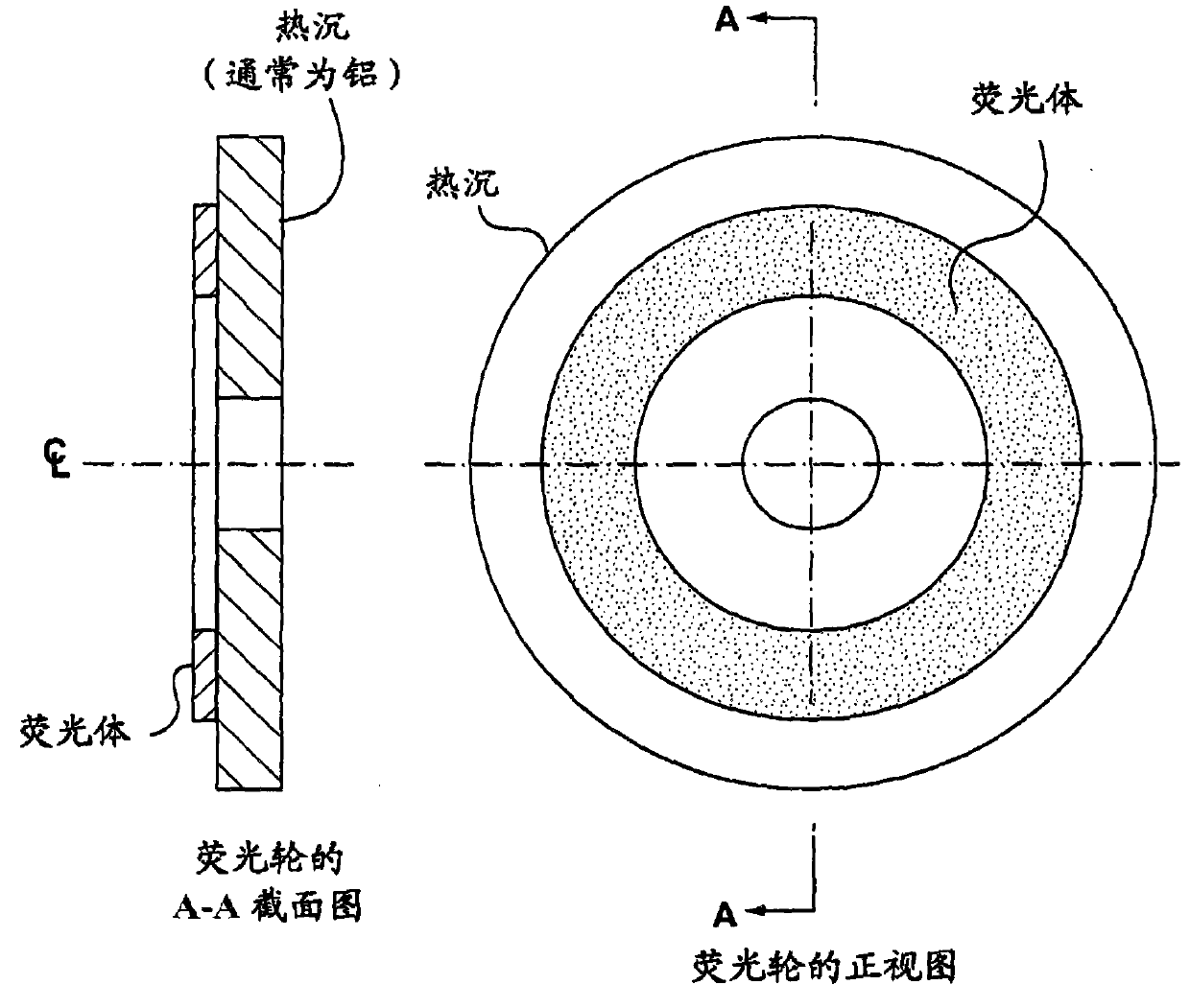
[0038] Fig. 1 shows a front view of a lighting device in the prior art and a cross-sectional view thereof along line A-A. Specifically, the light emitting device includes a phosphor wheel, and the phosphor wheel includes a heat sink (about 1 mm in thickness) and a luminescent material such as a phosphor (about 0.2 mm in thickness). The heat sink may comprise aluminum, which has a higher CTE (about 22 μm / m-K) than that of the phosphor (about 6-7 μm / m-K), which causes the light emitting device to generate heat when the temperature of the light emitting device increases during operation. Mechanical failure.

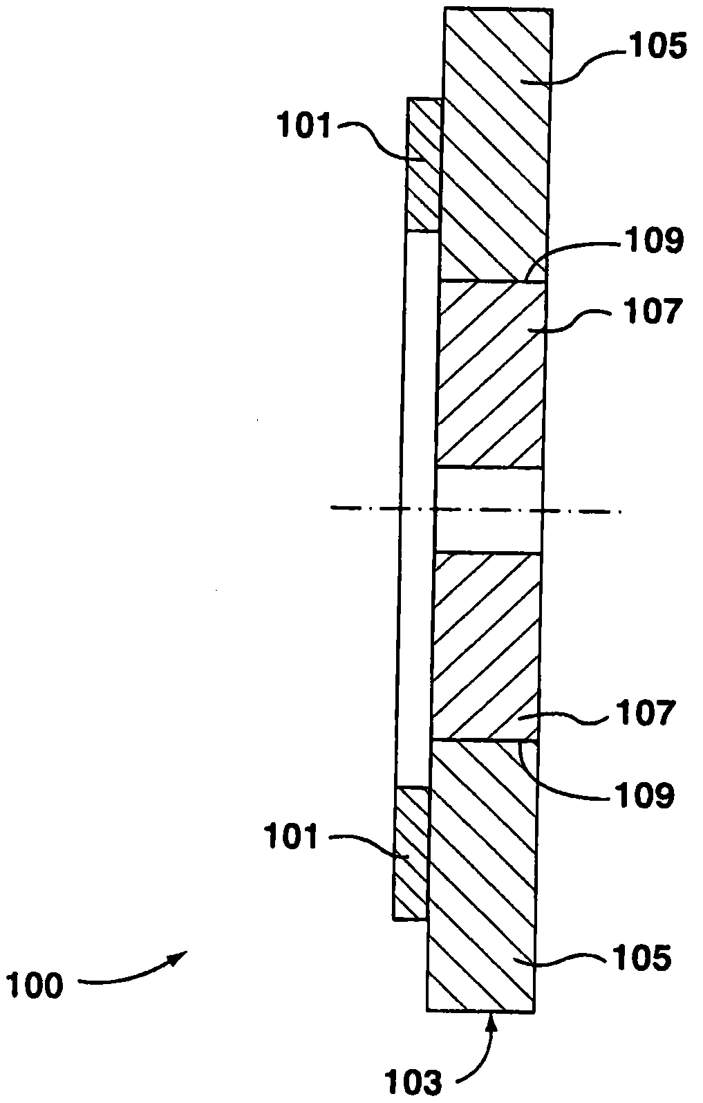
[0039] see next figure 2 , which shows a cross-sectional view of a device 100 similar to that of FIG. , the first material 105 includes a first coefficient of thermal expansion (CTE), and the second material 107 is bonded to the first material 105 at an interface 109 between the second material and the first material, the second material 107 includes With a second CTE low...


PUM


Abstract

A light emitting device having a heat sink composed of two materials is provided. The device includes: a luminescent material; and a heat sink comprising: a first material configured to cool the luminescent material, the first material including a first coefficient of thermal expansion (CTE); and a second material, the second material at The second material is bonded to the first material at an interface between the first material, the second material includes a second coefficient of thermal expansion lower than the first coefficient of thermal expansion, and the luminescent material is bonded to the first material but not to the second material.

Description

technical field [0001] This description mainly relates to lighting systems, and in particular to lighting devices having heat sinks (ie heat sinks) composed of two materials. Background technique [0002] In light-excited lighting systems such as laser-ceramic phosphor systems, laser-quantum dot systems, etc., the combination of luminescent materials and heat sinks (ie heat sinks, heat sinks) will fail due to thermal expansion coefficient (CTE) mismatch. In other words, the thermal expansion coefficient of the heat sink is usually higher than that of the luminescent material (such as phosphor, quantum dot, etc.), so that as the temperature of the system increases during operation, the luminescent material expands at a lower rate than the heat sink, causing the system thermal-mechanical failure. Such problems can be addressed by controlling the power of the excitation light source, such as a laser, and / or by controlling the temperature of the system. However, controlling th...

Claims


Application Information

Patent Timeline
Patent Type & Authority Patents(China)
IPC IPC(8): F21V29/85
CPCG03B21/204F21V29/502F21V29/70F21V29/89G03B21/16F21Y2115/30F21Y2115/10Y10T29/49863Y10T29/49865F21V13/08F21V9/38F21V9/45F21V29/503F21V29/85
Inventor D·R·阿德玛G·希尔S·格思里D·帕斯特里克
Owner CHRISTIE DIGITAL SYST USA INC
Features
  • R&D
  • Intellectual Property
  • Life Sciences
  • Materials
  • Tech Scout
  • Unparalleled Data Quality
  • Higher Quality Content
  • 60% Fewer Hallucinations
Learn More