
Ultra-wideband antenna

An ultra-wideband antenna and microstrip feeder technology, which is applied to antennas, devices that make the antennas work in different bands at the same time, and the structure of radiating elements, etc. and other problems, to achieve the effect of improving standing wave ratio characteristics, improving impedance characteristics and simple structure

Active Publication Date: 2015-08-05
KUNSHAN ENDIAN COMM EQUIP CO LTD
View PDF6 Cites 1 Cited by
  • Summary
  • Abstract
  • Description
  • Claims
  • Application Information

AI Technical Summary

Problems solved by technology

[0003] With the advancement of mobile communication technology and the rapid expansion of mobile Internet, the ultra-broadband wireless communication system continues to expand, and multiple systems coexist, and the working frequency bands of various systems are also expanding, from the early GSM 1800 (1710 ~ 1880MHz); PCS1850~1990MHz, UMTS 1920~2170MHZ, mid-term TD-SCDMA (1880~1920MHz, 2010~2025MHz, 2300~2400MHz); Wimax and TD-LTE communication frequency band (2300~2690MHz), and now LTE-A (3500MHz ~3600MHz), so that the number of antennas and corresponding equipment increases, which increases the operating costs of telecom operators
[0004] However, in the existing technical solutions, the omnidirectional antenna composed of half-wave dipoles has narrow bandwidth, as document 1. "A broadband printed dipole and a printed array for base station applications" (IEEE Antennas and Propagation Society International symposium, 2008 The bandwidth of the antenna model in :1-4) is 41%, and the bandwidth of the antenna model in Document 2. "Printed broadband dipole antenna with tapered arms for multi-band applications" (Signals Systems and Electronics, International Symposium, 2010: 1-3) 48%

Method used


Image

  • Ultra-wideband antenna
  • Ultra-wideband antenna
  • Ultra-wideband antenna

Examples


Embodiment 1

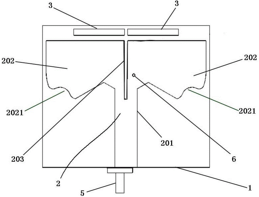
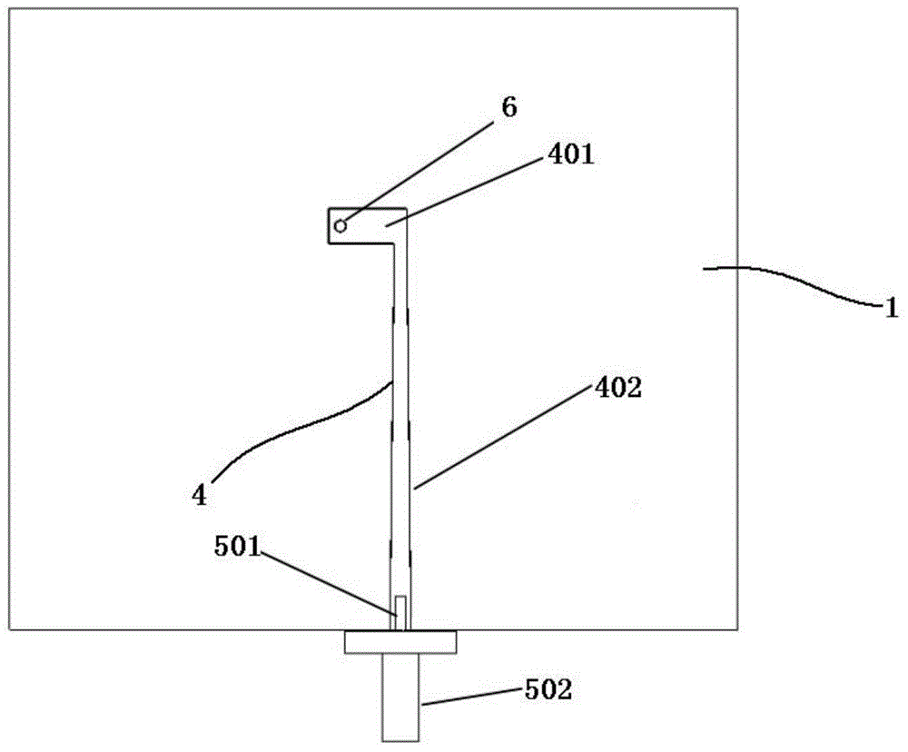
[0030] like figure 1 and figure 2 As shown, an ultra-wideband antenna includes a dielectric substrate 1, a radiator 2, two main parasitic units 3, a microstrip feeder 4 and a coaxial connector 5. The dielectric substrate has a first surface and a second surface opposite to it. On the surface, the radiator includes a feed-in part 201 and two radiation arms 202, the radiator 2 and the two main parasitic units 3 are arranged on the first surface, and the microstrip feeder 4 is arranged in an L shape on the first surface. On the second surface, the coaxial connector 5 is fixed on the bottom of the dielectric substrate 1, and the feed-in part 201 of the radiator 2 and the vertical part 402 of the microstrip feed line are connected with the same The shaft connector 5 is electrically connected.

[0031] The total length of the two radiating arms 202 is 0.4λ 0 ~0.7λ 0 ;Width 0.15λ 0 ~0.3λ 0 (λ 0 is the center frequency of the working frequency band); the two radiating arms 202...

Embodiment 2

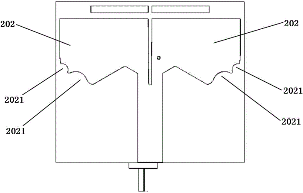
[0039] see image 3 and Figure 4 , this embodiment 2 includes all the technical features of embodiment 1, the difference is that two U-shaped grooves 2021 are respectively formed at the ends of the two radiating arms 202; and the impedance of the upper end and the lower end of the microstrip feeder 4 is the same.

Embodiment 3

[0041] see Figure 5 , this embodiment 3 includes all the technical features of embodiment 1, the difference is that two strip-shaped secondary parasitic units 7 are also provided, and the two secondary parasitic units 7 are arranged on the back of the two main parasitic units 3 , and each secondary parasitic unit 7 is at a set distance from its corresponding main parasitic unit 3 . That is, a short secondary parasitic unit 7 is added at the main parasitic unit 3 . The secondary parasitic unit 7 can generate multiple resonance frequency points, thereby widening the frequency bandwidth of the antenna.


PUM


Abstract

The invention discloses an ultra-wideband antenna, comprising a medium substrate, a radiator, two main parasitic units, a microstrip feeder, and a coaxial connector. The medium substrate is provided with a first surface and a second surface which is opposite to the first surface. The radiator comprises a feed-in portion, and two radiation arms. The radiator and the two main parasitic units are arranged on the first surface. The microstrip feeder is arranged on the second surface in an L shape. The coaxial connector is fixedly arranged on the bottom of the medium substrate. The feed-in portion of the radiator and the vertical part of the microstrip feeder are electrically connected with the coaxial connector at the same time. Through arranging the two radiation arms which are distributed symmetrically, and forming a gradually changing gap between the two radiation arms, impedance characteristic of an antenna is improved, and impedance bandwidth of the antenna is broadened. Through forming at least a groove on the tail end of each radiation arm, high-frequency standing-wave ratio characteristic can be improved, and circumferential distribution of a plurality of groups of radiation arms is convenient.

Description

technical field [0001] The invention relates to a communication antenna, in particular to an ultra-wideband antenna. Background technique [0002] Ultra-wideband antenna communication technology (UWB) generally refers to a radio technology with a signal bandwidth greater than 1.5 GHz or a bandwidth ratio (the ratio of signal width to center frequency) greater than 25%. The UWB antenna is a key component in the UWB wireless communication system, and the performance of the antenna will directly affect the performance of the entire system. [0003] With the advancement of mobile communication technology and the rapid expansion of mobile Internet, the ultra-broadband wireless communication system continues to expand, and multiple systems coexist, and the working frequency bands of various systems are also expanding, from the early GSM 1800 (1710 ~ 1880MHz); PCS1850~1990MHz, UMTS 1920~2170MHZ, mid-term TD-SCDMA (1880~1920MHz, 2010~2025MHz, 2300~2400MHz); Wimax and TD-LTE communi...

Claims


Application Information

Patent Timeline
IPC IPC(8): H01Q5/25H01Q1/36H01Q5/335H01Q5/378
Inventor 董必勇林宏行
Owner KUNSHAN ENDIAN COMM EQUIP CO LTD
Features
  • Generate Ideas
  • Intellectual Property
  • Life Sciences
  • Materials
  • Tech Scout
  • Unparalleled Data Quality
  • Higher Quality Content
  • 60% Fewer Hallucinations
Learn More