Medical washing and disinfecting machine

A technology for cleaning and disinfecting and cleaning liquid tanks, applied in the field of medical devices, can solve the problems of insufficient sterilization and disinfection of medical devices, inability to complete the task of cleaning medical devices, and inability to realize the cleaning and disinfection process, so as to improve the degree of disinfection and sterilization, improve efficiency, Efficient effect

Inactive Publication Date: 2015-08-12
广州涞泊锐科技股份有限公司
4 Cites 27 Cited by

AI-Extracted Technical Summary

Problems solved by technology

Most of the existing medical disinfection cabinets have single functions, cannot realize a complete cleaning and disinfection process, and generally only use one disinfection method, resulting in insufficient sterilization and disinfection of medical devices
[0003] With the improvement of the domestic medical level in recent years, the requirements for the hygiene and cleanliness of medical devices are getting higher and higher. Medical devices with high cleanliness play an important role, which can avoid external infections caused by the use of devices to patients, which is beneficial The healing of wounds puts higher demands on medical disinfecti...

Abstract

The invention discloses a medical washing and disinfecting machine. The medical washing and disinfecting machine comprises a cabinet body, a cabinet door, placing supports, a cleaning system, ultraviolet ray sterilization light sources, an electric steam generator, a waste discharge system, and a controller; the cabinet body is divided into an inner layer and an outer layer, and a cavity is formed between the inner layer and the outer layer; a thermal insulation layer is arranged in the cavity close to the inner layer of the cabinet body; the inner side frame of the cabinet door is provided with a sealing rubber ring; the cleaning system comprises a sterile water tank, a cleaning fluid tank, a water pump, a water pipe, and nozzles; the ultraviolet ray sterilization light sources are arranged on the top part of the inner part of the cabinet body; and the electric steam generator comprises an electric steam generator main body and a steam delivery pipe. The medical washing and disinfecting machine can be used for one time cleaning of medical apparatus, avoiding artificial cleaning of medical apparatus, and reducing labor force; and ultraviolet disinfection and sterilization, and high pressure steam disinfection and sterilization are adopted, so that efficiency is high.

Application Domain

Technology Topic

Image

  • Medical washing and disinfecting machine
  • Medical washing and disinfecting machine
  • Medical washing and disinfecting machine

Examples

  • Experimental program(1)

Example Embodiment

[0025] Specific implementation plan
[0026] The technical solutions in the embodiments of the present invention will be clearly and completely described below in conjunction with the accompanying drawings in the embodiments of the present invention. Obviously, the described embodiments are only a part of the embodiments of the present invention, rather than all the embodiments. Based on the embodiments of the present invention, all other embodiments obtained by those of ordinary skill in the art without creative work shall fall within the protection scope of the present invention.
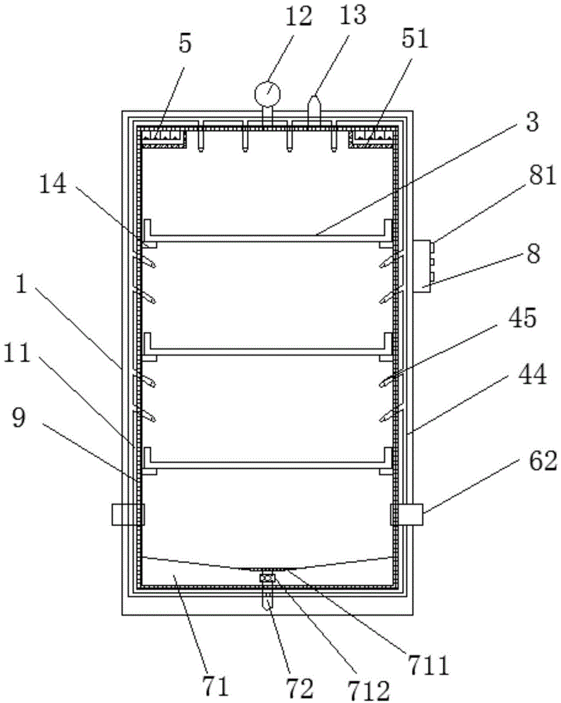
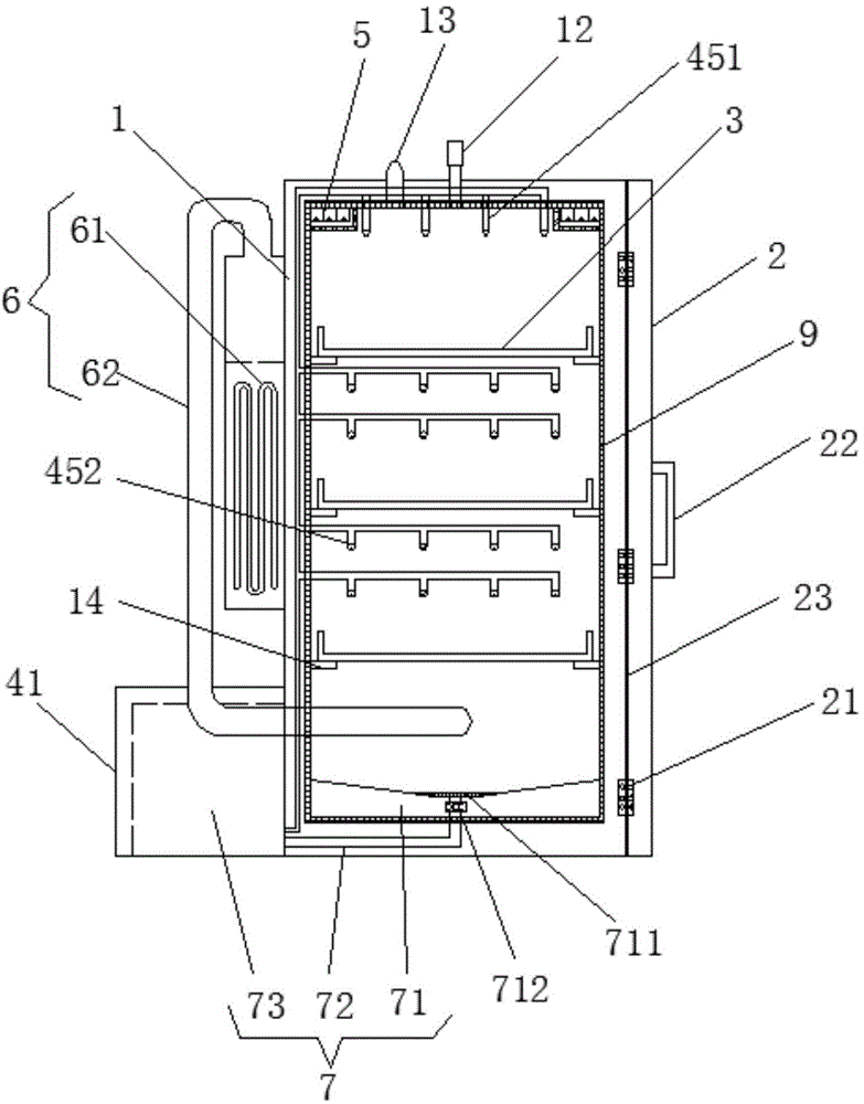
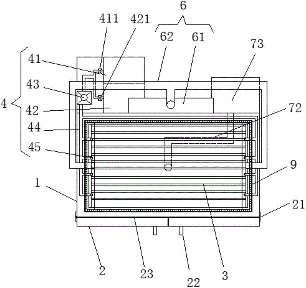
[0027] See Figure 1-3 , The present invention provides a technical solution: a medical cleaning and disinfection machine, including cabinet 1, cabinet door 2, placing bracket 3, cleaning system 4, ultraviolet sterilization light source 5, electric steam generator 6, sewage system 7 and control The cabinet door 2 is installed on the front of the cabinet body 1 through the hinge 21. The handle 22 is installed at the middle position of the outside of the cabinet door 2, and the cabinet door 2 is a split design. The inner side frame of the cabinet door 2 is fitted with The sealing rubber ring 23 can avoid steam overflow and improve the sterilization effect. The cabinet 1 adopts a double-layer design, which is divided into an inner layer and an outer layer, and a cavity 11 is left in the middle. The inside of the cavity 11 is close to the inner layer of the cabinet 1 and is provided with a heat insulation layer 9, which can be sterilized by high pressure steam When isolating the internal heat, a pressure gauge 12 and a safety valve 13 are installed on the top of the outer layer of the cabinet 1. The pressure gauge 12 and the safety valve 13 are in communication with the inside of the cabinet 1, the pressure gauge 12 can detect the internal pressure information in real time, and the safety valve 13 can release the pressure when the internal pressure is too high, which increases safety. The inner side wall of the cabinet 1 is provided with slide rails 14 in layers, and the slide rail 14 is installed on the inner side wall of the cabinet 1 with at least one layer. In the embodiment of the figure, there are three layers. The placing bracket 3 adopts a strip hollow design and is movably placed on the sliding rail 14 for placing medical instruments. The cleaning system 4 includes a sterile water tank 41, a cleaning liquid tank 42, a water pump 43, a water pipe 44, and a spray head 45. The sterile water tank 41 is connected to the water inlet of the water pump 43 through a water pipe 44, and whether the outlet of the sterile water tank 41 is installed The bacteria water tank electromagnetic control valve 411 is used to control the opening and closing of the sterile water tank 41, and the sterile water tank electromagnetic control valve 411 is electrically connected to the controller 8. The cleaning liquid tank 42 is connected to the water inlet of the water pump 43 through a water pipe 44, and a cleaning liquid tank electromagnetic control valve 421 is installed at the outlet of the cleaning liquid tank 42 to control the opening and closing of the cleaning liquid tank 42 and the cleaning liquid tank is electromagnetically controlled. The valve 421 is electrically connected to the controller 8. The water pump 43 is electrically connected to the controller 8. The nozzle 45 is installed at the upper position of the bracket 3 on each layer. The nozzle 45 includes a top nozzle 451 and a side wall nozzle 452. The top nozzle 451 is installed on the top of the cabinet 1 and above the corresponding placement bracket 3. , And the top nozzle 451 is provided in at least one row, and there are two rows in the embodiment of the figure. The side wall sprinkler 452 is installed on the inner side wall of the cabinet 1 and is located above the corresponding placing bracket 3, and the side wall sprinkler 452 is arranged at least one row above the corresponding placing bracket 3. In this figure There are two rows in the embodiment. The spray head 45 adopts a high-pressure spray head that can spray a dispersed water column, which can uniformly and efficiently clean the medical equipment under it. The nozzle 45 is connected to the outlet of the water pump 43 through a water pipe 44, and the water pipe 44 adopts a hidden design in the section connecting the nozzle 45 and the water pump 43, and is installed inside the cavity 11 of the cabinet 1, which not only improves the service life of the water pipe , And can increase the overall aesthetics. The ultraviolet sterilization light source 5 is located on the top of the inside of the cabinet 1 and is electrically connected to the controller 8. The ultraviolet sterilization light source 5 is installed inside the sealed high temperature and high pressure resistant glass 51 to avoid the high temperature and high pressure steam environment from giving the ultraviolet sterilization light source 5 The damage caused. The electric steam generator 6 includes a steam generator body 61 and a steam delivery pipe 62. The steam generator body 61 is installed on the back side wall of the outer layer of the cabinet 1, and is electrically connected to the controller 8. The steam inlet end is connected to the steam outlet of the steam generator body 61, and the steam outlet end of the steam delivery pipe 62 is connected to the cabinet 1 from both sides of the cabinet 1 and communicates with the inside of the cabinet 1 for conveying large quantities High temperature steam. The sewage system 7 includes a sewage collection tank 71, a sewage pipe 72 and a sewage collection tank 73. The sewage collection tank 71 is installed at the bottom of the cabinet 1, and the sewage collection tank 71 adopts a design method of sloping all around to the center. This design is convenient Sewage gathers in the middle to facilitate sewage discharge. The sewage collection tank 71 is equipped with a dirt filter 711 above the outlet located in the center, which can filter some large-volume dirt and avoid clogging of the sewage pipe 72. The dirt filter 711 is removable. design. The sewage collection tank 71 is connected to the sewage collection tank 73 through a sewage pipe 72, and a sewage electromagnetic control valve 712 is installed at the outlet of the sewage collection tank 71. The sewage electromagnetic control valve 712 can prevent steam from overflowing from the sewage pipe 72 when it is closed. The sewage electromagnetic control valve 712 is electrically connected to the controller 8. The controller 8 is installed on the outer side of the cabinet 1.
[0028] Figure 4 It is a block diagram of the control principle of the present invention, such as Figure 4 As shown, the controller 8 includes a control adjustment button 81, a control module 82, a timer 83, and a single-chip processor 84. The control adjustment button 81 is connected to the control module 82. By controlling the adjustment button 81, the working time under different processes and related Set up. The control module 82 is connected to the single-chip processor 84, and the timer 83 is bidirectionally connected to the single-chip processor 84, which can time the working process of the single-chip processor 84. The single-chip processor 84 is respectively connected to the aseptic water tank electromagnetic control valve 411, the cleaning liquid tank electromagnetic control valve 421, the water pump 43, the ultraviolet sterilization light source 5, the electric steam generator main body 61 and the sewage electromagnetic control valve 712, for controlling the power off And turn on.
[0029] Working principle: The staff sets the relevant values, the controller 8 first controls to open the cleaning liquid tank electromagnetic control valve 421, and at the same time opens the water pump 43, at this time, the nozzle 45 sprays the cleaning liquid to clean the medical equipment, and the process is over Then, the controller 8 controls the solenoid control valve 421 of the cleaning liquid tank to close, and at the same time opens the solenoid control valve 411 of the aseptic water tank, the nozzle 45 sprays sterile water to rinse the medical instruments. After this process is over, the controller 8 controls to close The aseptic water tank electromagnetic control valve 411 and the water pump 43 are turned on at the same time to turn on the ultraviolet sterilization light source 5 to perform ultraviolet sterilization on medical equipment. After this process, the controller 8 turns off the ultraviolet sterilization light source 5 and closes the sewage electromagnetic control valve 712 at the same time, and then turns on The main body 61 of the electric steam generator performs high-temperature steam sterilization on medical instruments. After completion, the main body 61 of the electric steam generator is controlled to close, and the entire cleaning and disinfection process ends.
[0030] The above are only the preferred embodiments of the present invention, and do not limit the technical scope of the present invention. Therefore, any minor modifications, equivalent changes and modifications made to the above embodiments based on the technical essence of the present invention are still valid. It belongs to the scope of the technical solution of the present invention.

PUM

no PUM

Description & Claims & Application Information

We can also present the details of the Description, Claims and Application information to help users get a comprehensive understanding of the technical details of the patent, such as background art, summary of invention, brief description of drawings, description of embodiments, and other original content. On the other hand, users can also determine the specific scope of protection of the technology through the list of claims; as well as understand the changes in the life cycle of the technology with the presentation of the patent timeline. Login to view more.

Similar technology patents

Battery level indication by portable telephone

InactiveUS20120190305A1Reduce usageWireless architecture usageElectrical testingState of chargeHuman–machine interface
Owner:STMICROELECTRONICS SRL

Seal arrangement

Owner:ROLLS ROYCE PLC

Classification and recommendation of technical efficacy words

  • Reduce usage
  • Improve efficiency

System and method of model-driven development using a transformation model

InactiveUS20060064667A1Reducing model complexityReduce usageModel driven codeSpecific program execution arrangementsModel driven developmentGraphical model
Owner:FREITAS JOSE DE

Telecommunications networks and devices

InactiveUS20110263274A1Reduce usageNeed can be usedAssess restrictionNetwork topologiesBroadband connectionBase station
Owner:VODAFONE GRP PLC
Why Eureka
Try Eureka