Reagent continuous quantitative injection device

A quantitative injection and reagent technology, applied in the direction of dissolving, mixing machines, chemical instruments and methods, etc., can solve the problems of low injection efficiency of titrators, and achieve the effect of improving injection efficiency

Inactive Publication Date: 2015-08-12
OCEANOGRAPHIC INSTR RES INST SHANDONG ACAD OF SCI
View PDF6 Cites 3 Cited by
  • Summary
  • Abstract
  • Description
  • Claims
  • Application Information

AI Technical Summary

Problems solved by technology

[0004] In order to solve the technical problem of low injection efficiency of the existing microfluidic quantitative injection using mechanical

Method used


Image

  • Reagent continuous quantitative injection device
  • Reagent continuous quantitative injection device

Examples


Embodiment 1

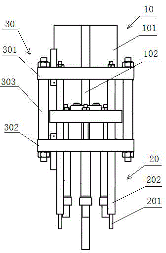
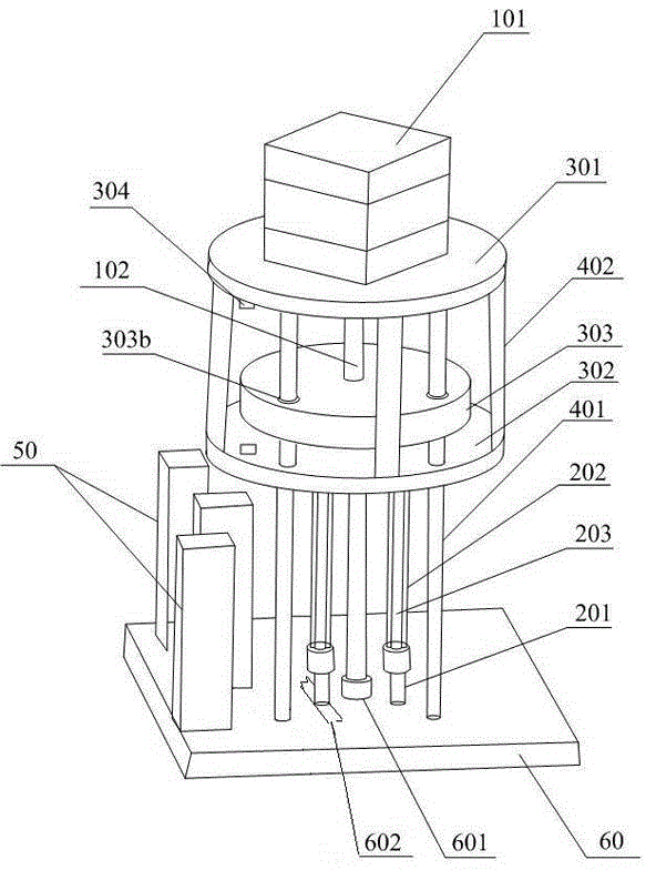
[0017] Embodiment 1, this embodiment proposes a continuous quantitative injection device for reagents, such as figure 1 As shown, it includes a power mechanism 10, at least one syringe 20, and a support connection mechanism 30. The support connection mechanism 30 includes an upper fixing plate 301, a lower fixing plate 302, and an adapter plate 303. The power mechanism 10 includes a motor 101 and the power output shaft 102, the syringe 20 includes a needle 201, a syringe 202, a piston rod 203, and a piston 204 fixed at the end of the piston rod 203, and the upper fixing plate 301 is fixed on the micro Above the flow control chip 60, the lower fixing plate 302 is located below the upper fixing plate 301, and is fixedly connected to the upper fixing plate 301 through a connecting rod 402, and the adapter plate 303 is located on the upper fixing plate 301 and the lower fixing plate 302, and the adapter plate 303 is provided with a guide hole 303b for allowing the support rod 401 ...


PUM


Abstract

The invention discloses a reagent continuous quantitative injection device. The device comprises a power mechanism, at least one injection syringe and a support connection mechanism. The support connection mechanism comprises an upper fixing plate, a lower fixing plate and an adapter plate. The power mechanism comprises a motor and a power output shaft. The injection syringe comprises a syringe needle, a syringe cylinder, a piston rod and a piston fixed to the end of the piston rod. The upper fixing plate is fixed above a microfluidic chip by a support rod. The lower fixing plate is located below the upper fixing plate and is fixedly connected to the upper fixing plate by a connection rod. The device utilizes the power mechanism and the at least one injection syringe. The power mechanism is controlled by an upper computer and drives the injection syringe so that an injection process is finished. The device realizes continuous automatic injection. The power mechanism can synchronously drive one or more syringes so that injection efficiency is further improved.

Description

technical field [0001] The invention relates to an injection device, in particular to a reagent continuous quantitative injection device. Background technique [0002] Microfluidic technology is based on micro-electromechanical processing (MEMS) technology. The chip integrates micro-functional modules such as micro-channels, micro-electrodes, micro-pumps, micro-valves, micro-storage tanks, micro-detection modules and connectors into the chip through maintenance processing. Micro-total analysis system on materials. Compared with conventional chemical and biological analyzers, microfluidic chips are more efficient and quicker, save reagents and costs, and have high integration and high precision. applications have developed rapidly. [0003] The quantitative injection operation of microfluidics is the core of microfluidic chip analysis technology, and it is the premise of microfluidic chip to achieve reagent ratio mixing. So far, there is no specific injection technology f...

Claims


Application Information

Patent Timeline
IPC IPC(8): B01F15/04B01F15/02B01F13/00
Inventor 吴宁曹煊褚东志王昭玉马然吴丙伟张述伟孔祥峰张颖颖刘岩张颖高杨郭翠莲曹璐张国华范萍萍吕静程岩石小梅刘东彦侯广利尤小华
Owner OCEANOGRAPHIC INSTR RES INST SHANDONG ACAD OF SCI
Why Eureka
Try Eureka