Method used for preventing sand adhesion of sand mould castings, and sand mould prefabricated components

A technology of sand casting and prefabrication, which is applied to a method for preventing sand-sticking of sand-casting castings and the field of sand prefabrication. Concessionary effect

Inactive Publication Date: 2015-08-12
鞍山千钢机械制造有限公司
View PDF6 Cites 3 Cited by
  • Summary
  • Abstract
  • Description
  • Claims
  • Application Information

AI Technical Summary

Problems solved by technology

This method increases the cost of the mold and makes the molding difficult

Method used


Image

  • Method used for preventing sand adhesion of sand mould castings, and sand mould prefabricated components
  • Method used for preventing sand adhesion of sand mould castings, and sand mould prefabricated components
  • Method used for preventing sand adhesion of sand mould castings, and sand mould prefabricated components

Examples


Embodiment 1

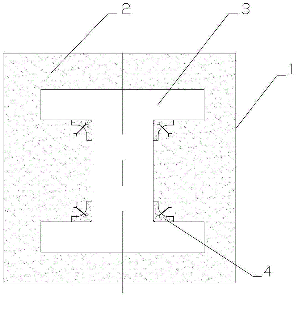
[0030] Such as figure 1 Shown, cast I-beam.

[0031] The method of preventing I-steel mold sand casting I-steel from sticking sand is to prefabricate the corresponding parts of the sand mold prefabricated parts in advance for the sand mold molding. The sand mold prefabricated parts are made of chrome ore in non-silica sand. The molding sand is compacted, and the prefabricated part is naturally fixed by the molding sand; the specific operation is as follows:

[0032] 1) Fill the sand box 1 with part of the molding sand 2;

[0033] 2) Judging from the I-beam structure, the four inner right-angle positions of the I-beam are prone to sand sticking;

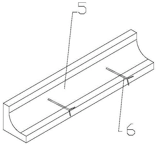
[0034] 3) Make I-steel sand mold prefabricated part 4 according to the inner right angle shape of I-steel, and I-steel sand mold prefabricated part 4 is a strip-shaped right-angled prefabricated part. Due to the long length of I-steel, the prefabricated parts are made into several fixed-length standards parts for splicing;

[0035...

Embodiment 2

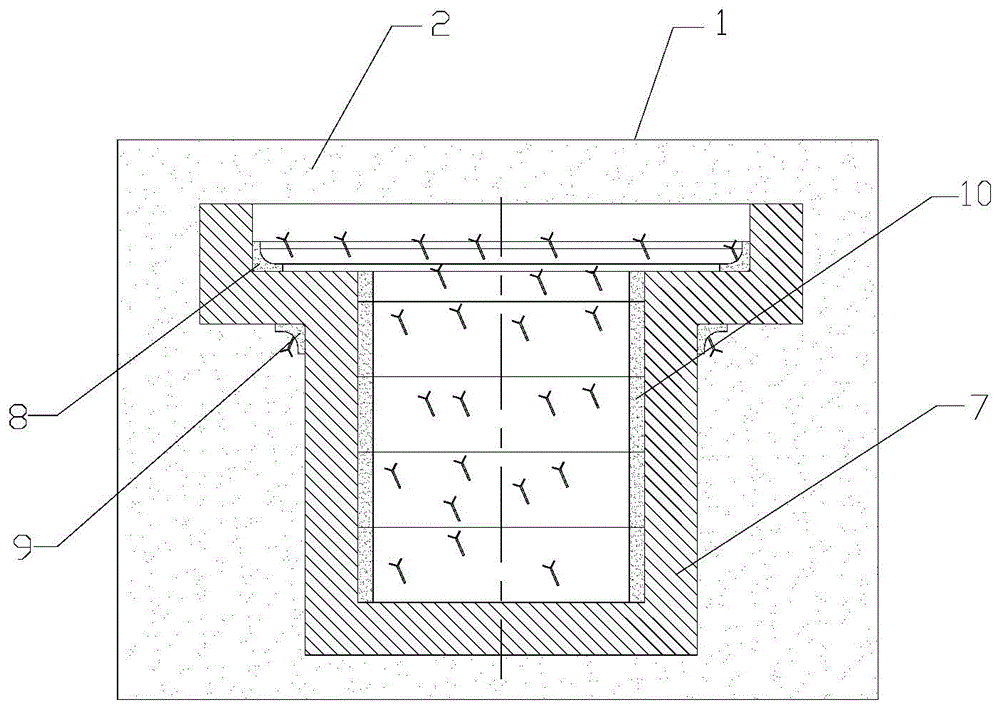
[0040] Such as image 3 As shown, casting stepped rotary workpiece

[0041] The method of preventing the sand casting of the stepped rotary part mold from sand casting is to prefabricate the sand mold prefabricated part in advance for the sand mold molding. The sand mold prefabricated part is made of zircon sand other than silica sand. The molding sand is compacted, and the prefabricated part is naturally fixed by the molding sand; the specific operation is as follows:

[0042] 1) Fill the sand box 1 with part of the molding sand 2;

[0043] 2) According to the structure of the stepped rotary workpiece, it is judged that the inner and outer stepped straight mouths of the stepped rotary workpiece and the inner wall of the cylinder are prone to sand sticking;

[0044] 3) Make inner and outer annular right-angle prefabricated parts 8 and 9 according to the shape of the inner and outer ladder straight mouths of the workpiece. The annular right-angle prefabricated parts can be cu...


PUM


Abstract

The invention relates to a method used for preventing sand adhesion of sand mould castings, and sand mould prefabricated components. Each of the sand mould prefabricated components comprises a prefabricated block and connecting claws; the connecting claws are embedded in the prefabricated block, and are firmly connected with the prefabricated block; and the two ends of each connecting claw are provided with Y-shaped support legs. According to the method, prefabrication of the sand mould prefabricated components corresponding to certain parts in sand mould modeling is carried out; in modeling processes, the sand mould prefabricated components are placed at corresponding parts, filling of moulding sand and pressing are carried out, and the connecting claws on the sand mould prefabricated components are mixed with the moulding sand so as to realize integration of the sand mould prefabricated components with the moulding sand. The special-type prefabricated components are fixedly arranged at the preset parts of sand moulding, so that casting sand adhesion and sand filling are avoided, local deformability and collapsibility are improved, local temperature is controlled, casting quality is increased, production cost is reduced, and operation is convenient. The sand mould prefabricated components are provided with universal R angles; plane standardization can be realized; and cutting and splicing can be carried out.

Description

technical field [0001] The invention relates to the field of sand casting, in particular to a method for preventing sand sticking of sand castings and a sand prefabricated part. Background technique [0002] 1. When manufacturing thick-section castings or large-scale castings, ordinary sand molds are not enough to withstand the high temperature of metal oxides, resulting in frequent defects such as sand inclusions and sand sticking on the surface of castings. In this case, the commonly used measures are local use of special The sand is stacked by hand. This method makes it difficult to control the amount, position and strength of special sand, resulting in waste of cost and lower casting quality. [0003] 2. In order to reduce sand sticking and sand wrapping of castings, improve local yield, and avoid local collapse, local temperature control is carried out. Partial use of sand cores is used to differentiate modeling materials. This method increases the cost of the mold, ...

Claims


Application Information

Patent Timeline
Patent Type & Authority Applications(China)
IPC IPC(8): B22C9/02
CPCB22C9/02
Inventor 鲍壮鲍猛李迎昀朱杰
Owner 鞍山千钢机械制造有限公司
Why Eureka
Try Eureka