Outer spherical clamp for grinding spherical gaskets

A technology of spherical gaskets and outer spherical surfaces, which is applied in the direction of grinding workpiece supports, etc., can solve the problems of not meeting the requirements of mass production, unreliable clamping, and easy slipping of spherical gaskets, etc.

Active Publication Date: 2015-08-12
TIANJIN JINHANG COMP TECH RES INST
View PDF10 Cites 3 Cited by
  • Summary
  • Abstract
  • Description
  • Claims
  • Application Information

AI Technical Summary

Problems solved by technology

The technical solution provided by the patent number 200810121605.0 and the patent name "Jig for Grinding Spherical Gaskets" solves the above technical problems, but the disadvantage is that it can only be used for spherical gaskets made of iron materials. For spherical gaskets made of copper materials, there is no way to use the above-mentioned patented technology to carry out grinding processing. Later, the applicant also adopted some methods to solve the above-mentioned technical problems, and also applied for related patents. Manually clamping the spherical gaskets one by one is slow and obviously cannot meet the requirements of mass production. What is more serious is that there are problems that the spherical gaskets cannot be reliably fixed on the fixture and the clamping is not reliable. Spherical gaskets are easy to come off during grinding

Method used


Image

  • Outer spherical clamp for grinding spherical gaskets
  • Outer spherical clamp for grinding spherical gaskets
  • Outer spherical clamp for grinding spherical gaskets

Examples


Embodiment Construction

[0014] The accompanying drawings show the technical solution of the present invention and its embodiments, and the relevant details and working principles of the embodiments will be further described below in conjunction with the accompanying drawings.

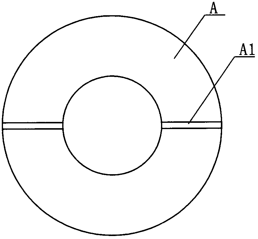
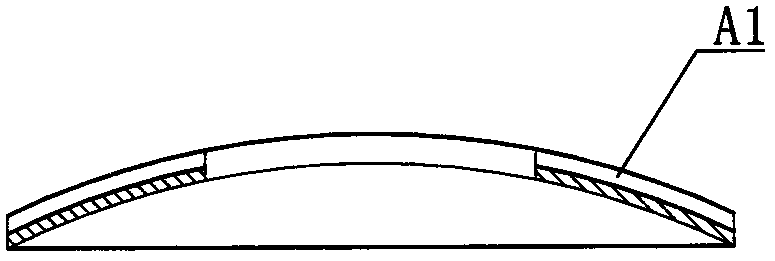
[0015] Such as Figure 1-2 As shown, the spherical gasket A ground by the present invention has an inner spherical surface, an outer spherical surface and a central inner hole, and the outer spherical surface is provided with a narrow groove A1 along the diameter direction of the spherical gasket.

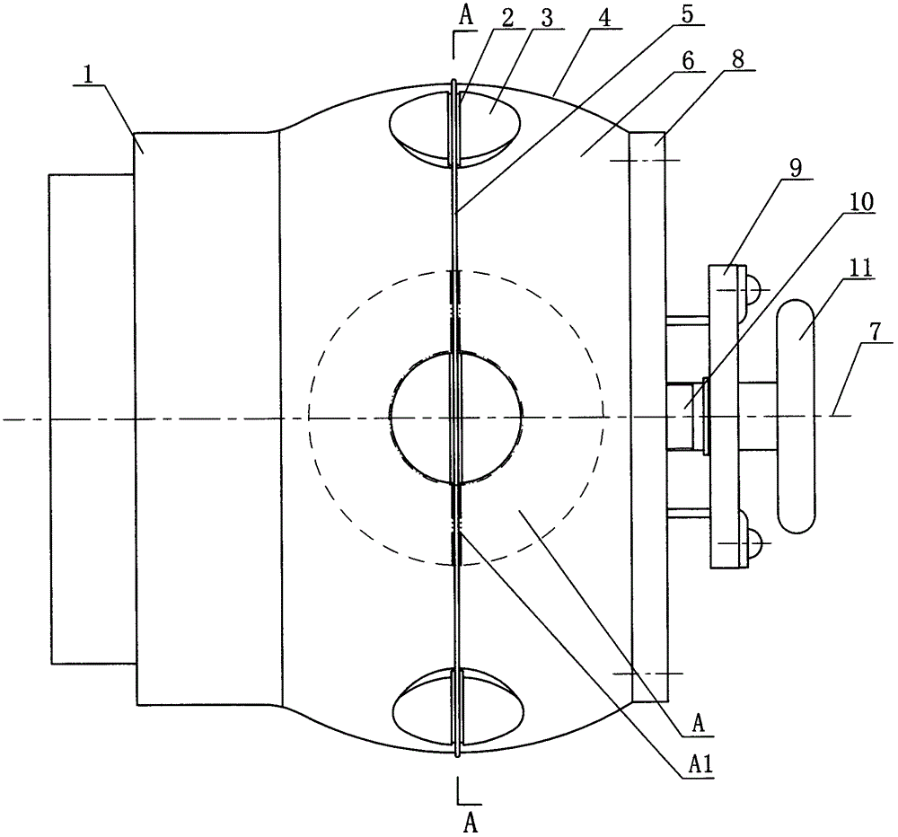
[0016] Such as Figure 3-6 As shown, a kind of outer spherical fixture for grinding spherical gaskets of the present invention includes a clamp body 6 with an outer spherical surface 4 and a flange 1 fixing the clamp body 6, and the outer spherical surface 4 radian of the clamp body 6 is connected with the spherical gasket A The radian of the inner spherical surface is the same, the top circumference of the outer spherical surface...


PUM


Abstract

The invention discloses an outer spherical clamp for grinding spherical gaskets. A narrow groove is formed in an outer spherical surface of each ground spherical gasket along the diameter direction; the clamp is characterized by comprising a clamp body, wherein a plurality of positioning pins are uniformly arranged on the circumference of the outer spherical surface of the clamp body; transverse grooves are formed in the tops of the positioning pins; in a grinding work process, the spherical gaskets arrayed on the outer spherical surface of the clamp body are tightened by a belt rope; the belt rope passes through the narrow grooves and the transverse grooves; the outer side end face of the clamp body is fixedly connected with an end cover; a movable plate and an adjusting screw rod are arranged on the outer side end face of the end cover; the adjusting screw rod is in threaded connection with the end cover; a rod end of the adjusting screw rod is provided with a hand wheel; the movable plate is rotationally arranged on the adjusting screw rod to do axial movement along with the adjusting screw rod; the two ends of the belt rope penetrate through the outer spherical surface of the clamp body to enter an inner hole of the clam body, and then penetrate through the end cover to be connected with the two centrally symmetric ends of the movable plate. The outer spherical clamp for grinding the spherical gaskets is used for grinding and machining the outer spherical surfaces of the spherical gaskets so that the rapid clamping and reliable fixation of the spherical gaskets can be realized and the working efficiency is improved.

Description

【Technical field】 [0001] The invention relates to a grinding fixture used for grinding the outer spherical surface of a spherical gasket. 【Background technique】 [0002] A spherical gasket is a gasket with an inner and outer spherical surface. The key to a spherical gasket lies in its spherical surface accuracy and smoothness. For quite a few spherical gaskets, the outer spherical surface has high requirements for accuracy and smoothness, and the outer spherical surface must be ground. Processing to achieve the required accuracy and finish. The technical solution provided by the patent number 200810121605.0 and the patent name "Jig for Grinding Spherical Gaskets" solves the above technical problems, but the disadvantage is that it can only be used for spherical gaskets made of iron materials. For spherical gaskets made of copper materials, there is no way to use the above-mentioned patented technology to carry out grinding processing. Later, the applicant also adopted some ...

Claims


Application Information

Patent Timeline
Patent Type & Authority Applications(China)
IPC IPC(8): B24B41/06
CPCB24B41/06
Inventor 薛瑞华
Owner TIANJIN JINHANG COMP TECH RES INST
Why Eureka
Try Eureka