Electroslag smelting method

An electroslag smelting and electrode technology, applied in the field of electroslag smelting, can solve the problems of low smelting production efficiency, unfavorable maintenance, breakage, etc., achieve good heating effect and efficiency, save equipment cost, and have simple and reasonable structure

Active Publication Date: 2015-08-12
宝武特冶航研科技有限公司
View PDF8 Cites 2 Cited by
  • Summary
  • Abstract
  • Description
  • Claims
  • Application Information

AI Technical Summary

Problems solved by technology

[0004] But this existing electroslag smelting furnace has the following defects: 1. Electroslag smelting is generally a process of batch smelting, but when the existing electroslag smelting furnace works with a single system, the smelting process needs to be time-consuming. The pre-electroslag loading and electrode clamping preparation are all time-consuming, which makes the overall smelting production efficiency relatively low
2. During the smelting process, the electrode is inserted into the electroslag and then energized and heated, and there is a huge temperature difference between the new billet and the molten pool when the electrode blanks are alternated. Explosion or block falling occurs; falling into molten steel in the mold below will affect production at least, and bring operational danger to electroslag smelting production
The more serious impact is that after the new electrode blank enters the molten pool, the temperature of the molten pool in the crystallizer will suddenly drop due to the excessive temperature difference between the end of the blank and the molten pool, breaking the normal melting environment.
As a result, quality defects such as shells, slag grooves, uneven composition, and impurities appear in the electroslag ingot, which seriously affects the smelting quality of the electroslag steel ingot.
3. In addition, the existing bottom water tank structure of the crystallizer still has the disadvantage of inconvenient disassembly and assembly, which is not conducive to maintenance

Method used


Image

  • Electroslag smelting method
  • Electroslag smelting method
  • Electroslag smelting method

Examples


Embodiment Construction

[0039] The present invention will be further described in detail below in conjunction with the best implementation mode and accompanying drawings.

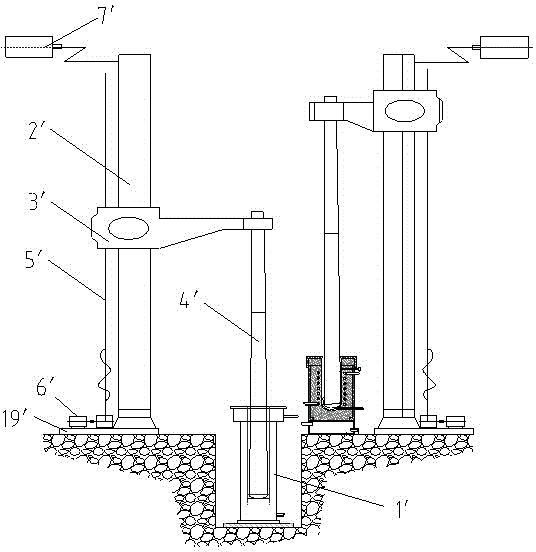
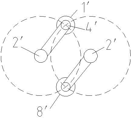
[0040] The key point of this electroslag smelting method is that two sets of electrode devices are arranged next to a crystallizer, and then the two sets of electrode devices are smelted by the crystallizer in turn. During the smelting process of one electrode device, the other electrode device performs installation of electrodes and The work of preheating the electrode, when the electrode device used in smelting is finished and the electrode is removed, re-feeding and the crystallizer is arranged, the preheated electrode is moved into the crystallizer for smelting, and this cycle realizes high-efficiency electroslag smelting.

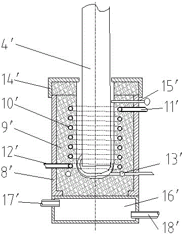
[0041] Specifically, in this embodiment, it is necessary to use such as Figure 1-3 The shown electroslag smelting electric furnace system is realized. The system includes a furnace-shaped crystallizer 1'...


PUM


Abstract

The invention discloses an electroslag smelting method. The electroslag smelting method is characterized in that two electrode devices are arranged beside a crystallizer and used for smelting in the crystallizer by turns, an electrode is installed on one electrode device and preheated when the other electrode device is used for smelting, an electrode of the electrode device used for smelting is moved away after smelting is completed, the preheated electrode is moved into the crystallizer for smelting after slag is fed again and the crystallizer is arranged well, and the process is repeated so as to achieve high-efficiency electroslag smelting. The electroslag smelting method has the advantages of high smelting efficiency and safety, excellent smelting effect, high efficiency, energy conservation, higher electroslag steel ingot smelting quality, great convenience in maintenance and replacement of the bottom water tank, lower maintenance cost and higher cooling efficiency.

Description

technical field [0001] The invention relates to an electroslag furnace smelting technology, in particular to an electroslag smelting method. Background technique [0002] Electroslag smelting furnace is a kind of equipment for electroslag remelting. The structure of the electroslag smelting furnace mainly includes a furnace-shaped crystallizer as a whole, and an electrode device located on one side of the crystallizer. The lower end of the crystallizer is provided with a bottom water tank for cooling. The electrode device includes a pillar, and the movable sleeve on the pillar is equipped with a cross arm. , the cross arm is facing the crystallizer to install the electrode extending down into the crystallizer. The electrode includes the upper part for the fixed part connected with the cross arm and the lower part for the smelting part that is integrated into the electroslag during smelting; it also includes the smelting part for controlling The lifting mechanism that lifts ...

Claims


Application Information

Patent Timeline
Patent Type & Authority Applications(China)
IPC IPC(8): C22B9/18C22B9/187
Inventor 吴建军秦洪伟赵伟
Owner 宝武特冶航研科技有限公司
Why Eureka
Try Eureka