A connection device and connection method for a pile leg and a pile shoe

A connection device and spud shoe technology, which is applied in sheet pile walls, water conservancy projects, artificial islands, etc., can solve the problems affecting the connection performance of pile legs and spud shoes, the stability of unstable connection platform, and the influence of platform stability, etc., to achieve Reduce pile pulling force, facilitate stable work, and reduce pile pulling force

Active Publication Date: 2016-09-14
COSCO SHIPPING SHIPYARD (NANGTONG) CO LTD
View PDF6 Cites 0 Cited by
  • Summary
  • Abstract
  • Description
  • Claims
  • Application Information

AI Technical Summary

Problems solved by technology

[0003] The mobile offshore operation platform lifts the platform above the sea level through the legs to avoid the equipment on the platform from being affected by the ocean wind, waves and currents during operation. Although some threaded connection methods and fusion welding methods can be used, they have disadvantages such as unstable connection and high cost.
The weldability of marine steel is poor, and cracks are prone to occur in the weld zone of ultra-thick plates, which seriously affects the connection performance of spud legs and spud cans
[0004] At the same time, in order to increase the contact area between the spud can and the seabed, the bottom of the spud can mostly adopts a larger area of ​​contact. In the static state, the spud can and the seabed have a better fit, and the contact surface has a greater adhesive force. This makes this type of spud boots require a larger pile pulling force at the moment when the piles are pulled out, which has a greater impact on the stability of the platform
[0005] The present invention is an improvement aimed at the defect of unstable connection and the influence of large pile pulling force on the stability of the platform that exists in the connection device of the spud legs and spud cans in the prior art.

Method used


Image

  • A connection device and connection method for a pile leg and a pile shoe
  • A connection device and connection method for a pile leg and a pile shoe
  • A connection device and connection method for a pile leg and a pile shoe

Examples


Embodiment 1

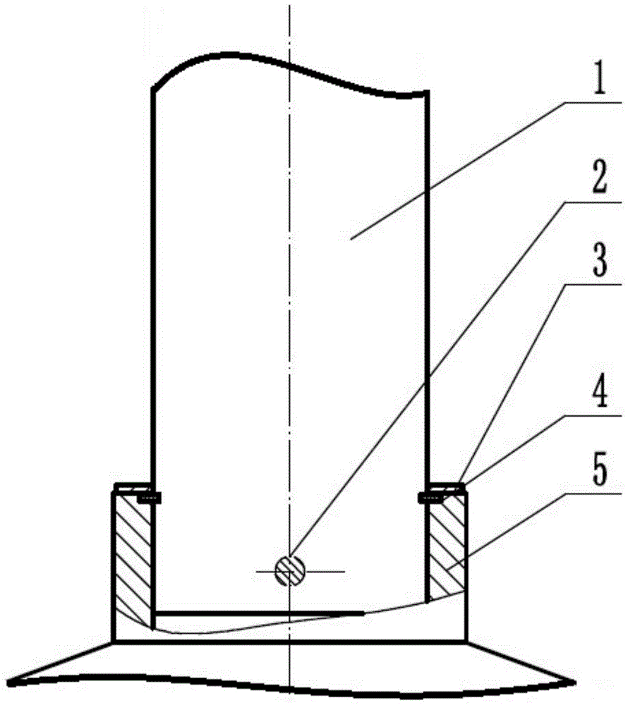
[0016] Example as figure 1 As shown, a connection device between a spud leg and a spud can, the device includes a spud leg 1 and a spud can, the spud can includes a spud can joint and a spud can joint hole, and the spud leg 1 is inserted into the spud can joint In the hole 5, the spud leg 1 and the spud shoe joint respectively include at least one pin hole, and at least one positioning pin 2 is correspondingly inserted into the pin hole. The spud shoe joint also includes a joint groove, and the joint groove is provided with a locking ring 4 and a cover plate 3, and the cover plate 3 abuts the locking ring 4 and is fixed to the locking ring 4 by bolts. The spud legs and the spud boots are connected and fixed through three parts. The first part is to insert the spud legs into the spud boots and fix the spud legs horizontally; the second part is to insert the positioning pins into the pin holes of the spud boots and spud legs, The pile leg is positioned axially; the third part i...

Embodiment 2

[0017] Example two such as figure 1 As shown, a method for connecting spud legs and spud cans: insert the spud legs 1 into the spud can joint holes 5 to reach the matching length, insert the positioning pins 2 into the pin holes of the spud legs 1 and the spud can joints respectively Press the locking ring 4 into the joint groove of the spud shoe joint, then place the cover plate 3 on the locking ring 4 and fix it with bolts; connect the spud legs 1 with the cover The plate 3 is welded, and the cover plate 3 and the spud shoe are welded. The spud legs and the spud boots are connected and fixed through three parts. The first part is to insert the spud legs into the spud boots and fix the spud legs horizontally; the second part is to insert the positioning pins into the pin holes of the spud boots and spud legs, Axial positioning of the pile leg; the third part is the horizontal fixation of the locking ring and the cover plate, the locking ring clamps the pile leg in the spud s...

Embodiment 3

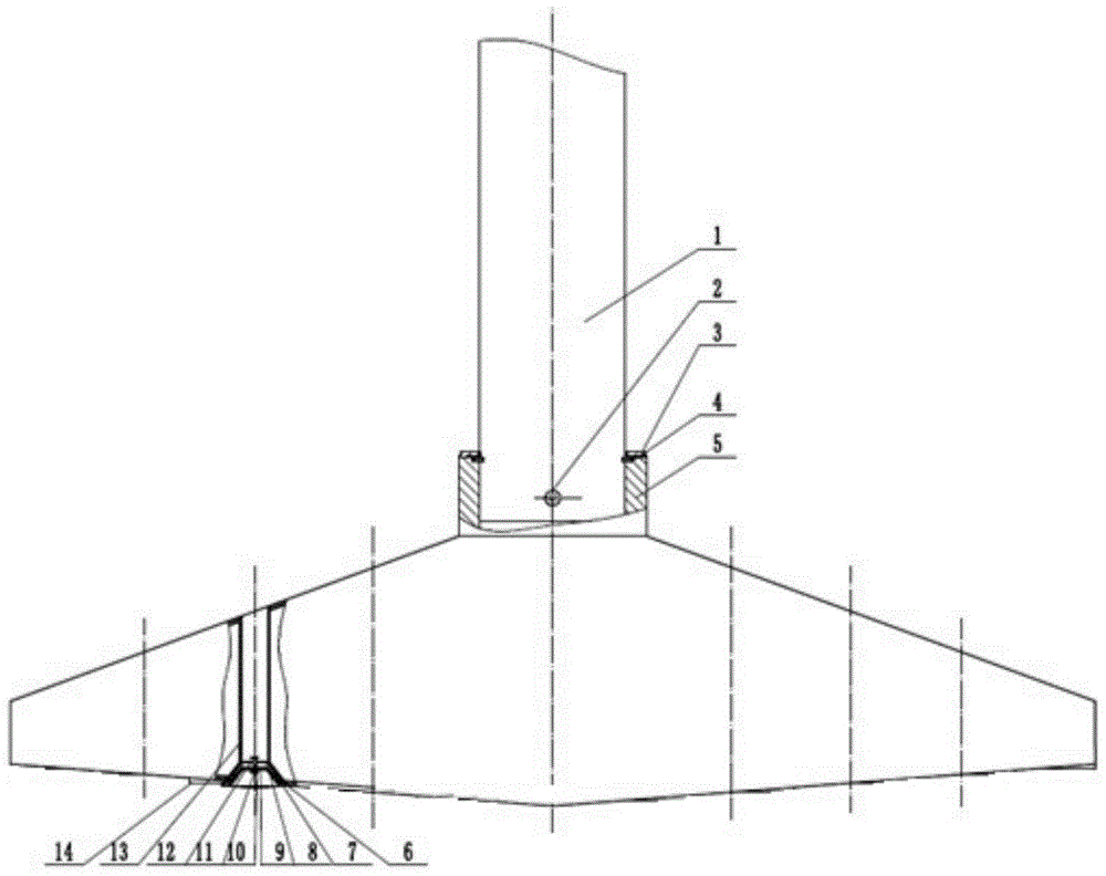
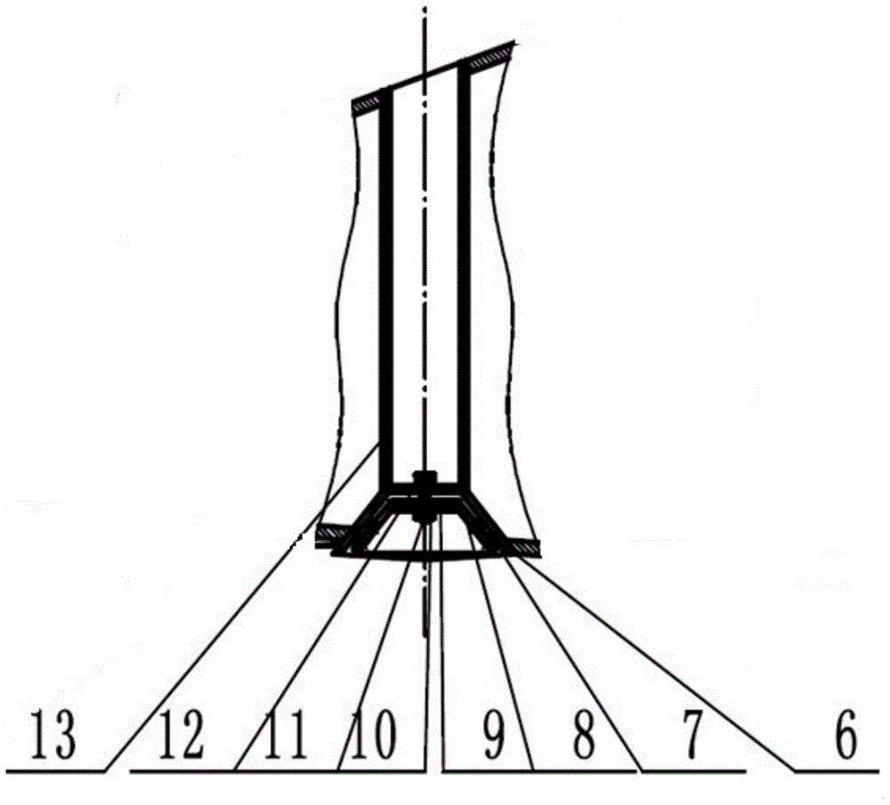
[0018] Embodiment three such as figure 2 As shown, a connection device between a spud leg and a spud can, the device includes a spud leg 1 and a spud can, the spud can includes a spud can joint and a spud can joint hole, and the spud leg 1 is inserted into the spud can joint In the hole 5, the spud leg 1 and the spud shoe joint respectively include at least one pin hole, and at least one positioning pin 2 is correspondingly inserted into the pin hole. The spud shoe joint also includes a joint groove, and the joint groove is provided with a locking ring 4 and a cover plate 3, and the cover plate 3 abuts the locking ring 4 and is fixed to the locking ring 4 by bolts. The spud legs and the spud boots are connected and fixed through three parts. The first part is to insert the spud legs into the spud boots and fix the spud legs horizontally; the second part is to insert the positioning pins into the pin holes of the spud boots and spud legs, The pile leg is positioned axially; t...


PUM


Abstract

The invention provides a connecting device and method for a pile leg and a pile shoe. The connecting device comprises the pile leg and the pile shoe. The pile leg is inserted into a pile shoe connector hole and positioned by a positioning pin. A pile shoe connector is provided with a connector groove which is provided with a locking ring. A cover plate is connected with the locking ring in an abutting mode and is fixed to the locking ring through a bolt. The pile shoe comprises a pervious pipe. The lower end of the pervious pipe is provided with a conical hole which is provided with an outer conical bowl. The outer conical bowl is movably connected with a pervious cover plate in the pervious pipe in the mode that a pin shaft penetrates through a lower lining plate, and is fixed by a nut. An annular rib plate is arranged at the bottom of the pile shoe by using the center of the bottom as the axis. The pile leg and pile shoe connecting stability is improved, the pile shoe supporting stability is improved, pile pulling force is reduced, and the workbench stability is improved.

Description

technical field [0001] The invention relates to the technical field of manufacturing marine engineering equipment, in particular to a connection device and method for spud legs and spud cans. Background technique [0002] The hull extends the spud legs into the seabed through the lifting system, and the spud legs are connected to the spud cans. The huge reaction force of the seabed to the spud cans makes the installation ship be lifted away from the sea surface to provide a stable working platform for marine operations. The quality of the connection between spud legs and spud cans will directly affect the standing stability of the hull and play a vital role in the operation process. [0003] The mobile offshore operation platform lifts the platform above the sea level through the legs to avoid the equipment on the platform from being affected by the ocean wind, waves and currents during operation. Although some screw connection methods and fusion welding methods can be used...

Claims


Application Information

Patent Timeline
Patent Type & Authority Patents(China)
IPC IPC(8): E02B17/02E02D5/52
Inventor 仇明颜建军李群孙博文施海华
Owner COSCO SHIPPING SHIPYARD (NANGTONG) CO LTD
Why Eureka
Try Eureka