Water pump shaft structure

A pump shaft and water pump technology, applied in the direction of pumps, pump components, non-variable-capacity pumps, etc., can solve the problems of weak pump shaft tensile strength, small positioning plane, poor pump shaft strength, etc., to shorten the processing time and process. , Ensure parallelism and strength, increase the effect of tensile strength

Inactive Publication Date: 2015-08-12
ZHEJIANG NANYUAN PUMP IND CO LTD
View PDF4 Cites 7 Cited by
  • Summary
  • Abstract
  • Description
  • Claims
  • Application Information

AI Technical Summary

Problems solved by technology

[0002] In the design structure of the existing vertical multi-stage pump, most of the matching parts of the pump shaft and the impeller adopt the cutting process. After cutting, the tensile strength of the pump shaft is weakened. Moreover, due to the cutting process, its size and tolerance are not easy Control, the surface roughness value is large, which greatly affects the original performance of the original polished rod
[0003] For the pump shaft structure of the existing vertical multi-stage pump, in the positioning of the impeller, some use cutting grooves, insert steel wires, and attach a positioning jacket to fix the axial size of the impeller. This design scheme, such as the width of the cutting groove, The strength of the pump shaft is poor; the cutting groove is small, the steel ring is thin, and the positioning strength of the impeller is poor
Some use the cutting method to cut out several small planes. Similarly, the positioning plane is small, the positioning strength of the impeller is weak, and the uniform flatness of several planes cannot be guaranteed, which affects the positioning strength of the pump shaft.

Method used


Image

  • Water pump shaft structure
  • Water pump shaft structure

Examples


Embodiment Construction

[0014] Combine below figure 1 and figure 2 Specific description embodiment:

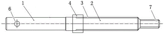
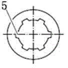
[0015] The pump shaft structure of the water pump, the pump shaft structure of the water pump includes the smooth end part 1 and the spline tooth end part 2 formed at one time by extrusion and stretching process, and the outer wall at the junction of the smooth end part 1 and the spline tooth end part 2 A number of external teeth 3 are arranged on the upper part; an impeller positioning sleeve 4 is provided at the junction of the smooth end part 1 and the spline tooth end part 3, and the inner wall of the impeller positioning sleeve 4 is provided with a center positioning one-time extrusion forming Inner tooth 5, inner tooth 5 matches with outer tooth 3. The light end part 1 is provided with a pin hole 6 for adjusting the installation size of the impeller in the pump. The spline tooth end portion 2 is provided with a screw thread 7 for fixing the axial position of the impeller.

[0016] When usi...


PUM


Abstract

The invention belongs to the technical field of tools for a water pump, and particularly relates to a water pump shaft structure. The water pump shaft structure comprises a smooth end and a spline tooth end which is formed in a one-off mode through an extruding and drawing process. Multiple outer teeth are arranged on the outer wall of the joint of the smooth end and the spline tooth end. An impeller locating sleeve is arranged at the joint of the smooth end and the spline tooth end. Inner teeth which are located at the center and formed in a one-off extruding and drawing mode are arranged on the inner wall of the impeller locating sleeve. The inner teeth are matched with the outer teeth. The water pump shaft structure has the advantages that the strength of the pump shaft can be guaranteed, the parallelism and the strength of locating of an impeller can also be guaranteed, the machining time is shortened, and the process is simple and rapid.

Description

technical field [0001] The invention belongs to the technical field of water pump appliances, and in particular relates to a pump shaft structure of a water pump. Background technique [0002] In the design structure of the existing vertical multi-stage pump, most of the matching parts of the pump shaft and the impeller adopt the cutting process. After cutting, the tensile strength of the pump shaft is weakened. Moreover, due to the cutting process, its size and tolerance are not easy control, the surface roughness value is large, which greatly affects the original performance of the original polished rod. [0003] For the pump shaft structure of the existing vertical multi-stage pump, in the positioning of the impeller, some use cutting grooves, insert steel wires, and attach a positioning jacket to fix the axial size of the impeller. This design scheme, such as the width of the cutting groove, The strength of the pump shaft is poor; the cutting groove is small, the steel ...

Claims


Application Information

Patent Timeline
Patent Type & Authority Applications(China)
IPC IPC(8): F04D29/043
CPCF04D29/043
Inventor 吴伟忠金记明
Owner ZHEJIANG NANYUAN PUMP IND CO LTD
Why Eureka
Try Eureka