Fan

A technology of a fan and a bending part, which is applied in the field of fan preparation, can solve the problems of airflow disorder, increased fan energy consumption, and high mute requirements, and achieves the effects of avoiding airflow disorder, avoiding eddy current shedding, and reducing eddy current.

Active Publication Date: 2015-08-12
GREE ELECTRIC APPLIANCES INC
View PDF5 Cites 1 Cited by
  • Summary
  • Abstract
  • Description
  • Claims
  • Application Information

AI Technical Summary

Problems solved by technology

[0003] At present, the fan blades, from the blade root curve to the blade top curve, are generally flat and smooth blade surfaces in order to obtain stable parameters and performance. However, it must be mentioned that this design often cannot achieve the best performance of the blades. , because during the rotation of the fan, one side of the blade is the suction side with lower pressure, and the other side is the pressure side with higher pressure, the airflow is drawn from the suction side of the blade to the pressure side and then blown out. Among them, especially at the part of the outer edge of the blade close to the blade tip curve, a backflow from the pressure surface to the suction surface is generated, forming a vortex around the outer edge. Curved flow gradually increases towards the trailing edge curve of the blade, which results in a louder fan
[0004] This not only causes the fan to fail to meet people's increasingly high requirements for quietness, but also increases the energy consumption of the fan due to the turbulence of the airflow formed by the vortex.

Method used


Image

  • Fan
  • Fan
  • Fan

Examples


Embodiment Construction

[0028] The core of the present invention is to provide a fan, so as to reduce the aerodynamic noise generated by the current fan when it rotates, and reduce the energy consumption of the fan during the rotation.

[0029] The following will clearly and completely describe the technical solutions in the embodiments of the present invention with reference to the accompanying drawings in the embodiments of the present invention. Obviously, the described embodiments are only some, not all, embodiments of the present invention. Based on the embodiments of the present invention, all other embodiments obtained by persons of ordinary skill in the art without making creative efforts belong to the protection scope of the present invention.
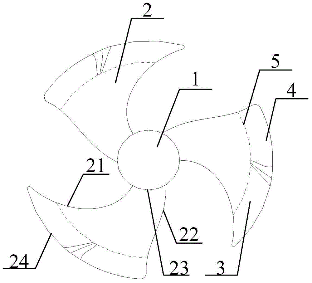
[0030] Firstly, the general idea of ​​the present invention is introduced, because the current fan blade root curve 23 to the blade top curve 24 are generally flat and smooth blade surfaces, but this design often cannot make the various performances o...


PUM


Abstract

The invention discloses a fan which comprises a hub and a plurality of blades arranged on the hub. By taking the axis of the hub as a circle center, and an intersection line of a circle with a radius R1 and each blade as a first boundary line, each first boundary line is positioned between the blade root curve and the blade top curve of the corresponding blade; a part between each first boundary line and the blade top curve of the corresponding blade and close to a front edge part of the corresponding blade is a front edge bending part; a part between each first boundary line and the blade top curve of the corresponding blade and close to a tail edge curve of the corresponding blade is a tail edge bending part; the parts, positioned on the corresponding first boundary line, of each front edge bending part and the corresponding tail edge bending part are connected with each other; each front edge bending part is bent towards a suction surface of the fan; each tail edge bending part is bent towards a pressure surface of the fan; and a transition curved surface used for connecting the corresponding front edge bending part and the corresponding tail edge bending part into a whole is arranged between each first boundary line and the blade top curve of the corresponding blade. The fan has the advantages that noise of the fan in the running process is effectively reduced and energy consumption is reduced effectively while the power capability of the fan is ensured.

Description

technical field [0001] The invention relates to the technical field of fan preparation, and more specifically, to a fan. Background technique [0002] Usually, a fan includes a hub and blades arranged on the hub, wherein the blades generally have multiple pieces, the hub of the fan is generally cylindrical, and the blades of the fan are composed of a leading edge curve, a trailing edge curve, a blade top curve and a blade root. The curve of the blade root is used for fixed connection with the hub, the curve of the leading edge is the curve at the front end along the rotation direction of the blade, the curve of the trailing edge is the curve at the rear end along the rotation direction of the blade, and the curve of the tip of the blade is the curve with The curve opposite the root curve. [0003] At present, the fan blades, from the blade root curve to the blade top curve, are generally flat and smooth blade surfaces in order to obtain stable parameters and performance. Ho...

Claims


Application Information

Patent Timeline
IPC IPC(8): F04D29/26F04D29/66
Inventor 龙斌华刘中杰
Owner GREE ELECTRIC APPLIANCES INC
Why Eureka
Try Eureka