Hot and cold water diverter valve
A diverter valve, cold and hot water technology, applied in the direction of valve details, multi-way valves, valve devices, etc., can solve the problems of easy backflow of cold water, poor diversion efficiency, piston misjudgment, etc., to speed up the time of hot water supply, improve The effect of shunting efficiency and improving accuracy
- Summary
- Abstract
- Description
- Claims
- Application Information
AI Technical Summary
Problems solved by technology
Method used
Image
Examples
Embodiment 1
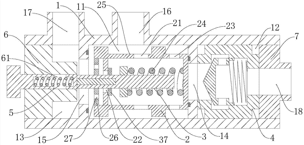
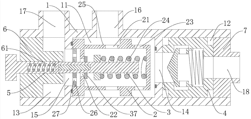
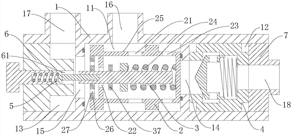
[0029] Such as Figure 1 to Figure 6 As shown, the cold and hot water diversion valve includes an outer sleeve 1 with both ends closed and hollow. The outer sleeve 1 is provided with a diversion cavity 11 and a return cavity 12 and a hot water cavity 13 respectively located on both sides of the diversion cavity 11. , The reflux chamber 12 communicates with the shunt chamber 11 through the first port 14, the hot water chamber 13 communicates with the shunt chamber 11 through the second port 15, and the reflux chamber 12 is provided with a one-way valve 4 communicating with the first port 14. , A hollow piston cylinder 2 is provided in the distribution chamber 11, and there is a certain gap between the outer wall of the piston cylinder 2 and the inner wall of the outer sleeve 1. The outer wall of the piston cylinder 2 is provided with an annular groove 25, and the outer sleeve 1 The cylinder wall is provided with a water inlet 16, a hot water outlet 17 communicating with the hot ...
Embodiment 2
[0033] This embodiment further defines the following on the basis of embodiment 1: The one-way valve 4 includes a valve body 41 with both left and right ends open, and the left end opening of the valve body 41 communicates with the first port 14, and The right end opening is in communication with the return water outlet 18. The valve body 41 is provided with a head 42 with a left end closing the right end opening and a third elastic member 44. The width of the closed end of the head 42 is greater than the width of the left end of the valve body 41. The head 42 A plurality of fourth through holes 43 communicating with the open end of the head 42 are provided on the side wall of the, and the third elastic member 44 acts on the open end of the head 42 so that the head 42 closes the left end opening of the valve body 41. When this embodiment is applied, such as Figure 5 As shown, water flows into the valve body 41 through the left end opening of the valve body 41. Due to the pressu...
Embodiment 3
[0035] This embodiment further defines the following on the basis of any one of Embodiments 1 to 2: The left end cover 6 is provided with mounting holes 61 penetrating the left and right end faces of the left end cover 6, and the elastic component 5 includes The temperature control rod 51, the second elastic member 52 and the pressure sleeve 53 are threadedly fitted in the hole 61. The temperature control rod 51 is placed in the end of the mounting hole 61 and is provided with an inner hole 54. The inner hole 54 and the pressure sleeve 53 are respectively sleeved Two ends of the second elastic member 52. In this embodiment, in order to improve the stability of the interaction between the elastic component 5 and the temperature sensing actuator 3, the left end cover 6 should be provided with sufficient thickness to ensure that the inner hole 54, the second elastic member 52 and the pressure sleeve 53 are all located in the installation 孔61. In addition, in order to realize the s...
PUM
 Abstract
Description
Claims
Application Information
 - R&D
- Intellectual Property
- Life Sciences
- Materials
- Tech Scout
- Unparalleled Data Quality
- Higher Quality Content
- 60% Fewer Hallucinations
Browse by: Latest US Patents, China's latest patents, Technical Efficacy Thesaurus, Application Domain, Technology Topic, Popular Technical Reports.
© 2025 PatSnap. All rights reserved.Legal|Privacy policy|Modern Slavery Act Transparency Statement|Sitemap|About US| Contact US: help@patsnap.com


