
Greedy sparse decomposition-based ECPT defect rapid detection method

A technology of sparse decomposition and detection method, applied in the direction of material defect testing, etc., can solve the problem of wrong number of defects, defect quantification accuracy needs to be improved, loss of data information, etc.

Inactive Publication Date: 2015-08-12
UNIV OF ELECTRONIC SCI & TECH OF CHINA
View PDF1 Cites 10 Cited by
  • Summary
  • Abstract
  • Description
  • Claims
  • Application Information

AI Technical Summary

Problems solved by technology

[0003] At present, ECPT’s detection and characterization of conductor material defects is still limited to the artificial selection of frame images recorded by thermal imaging cameras to identify and locate defects. This type of processing will lose a lot of data information, and cause inaccurate defect detection and positioning, and even wrongly determine defects. quantity
[0004] At the same time, the existing automatic defect analysis technology of ECPT, such as on November 13, 2013, the applicant proposed a pulsed eddy current thermal imaging defect automatic detection and identification method based on principal component decomposition and independent component decomposition (Chinese invention patent application publication No. CN103592333A, published on February 19, 2014), can automatically obtain multiple thermal pattern components, but requires additional processing to identify the thermal pattern components of defects, resulting in redundant calculations and its defect quantification accuracy needs to be improved

Method used


Image

  • Greedy sparse decomposition-based ECPT defect rapid detection method
  • Greedy sparse decomposition-based ECPT defect rapid detection method
  • Greedy sparse decomposition-based ECPT defect rapid detection method

Examples


Embodiment Construction

[0016] Specific embodiments of the present invention will be described below in conjunction with the accompanying drawings, so that those skilled in the art can better understand the present invention. It should be noted that in the following description, when detailed descriptions of known functions and designs may dilute the main content of the present invention, these descriptions will be omitted here.

[0017] When there are defects (such as cracks) in the conductor material, under the action of ECPT, the eddy current distribution at the defect position is different under electromagnetic induction. When the eddy current path is at a defect (such as a crack), the path of the eddy current will change accordingly to form various distribution areas of different eddy current densities near the crack. The eddy current density concentration area will be formed at both ends of the crack, and the eddy current density dispersion area will be formed on both sides of the crack. Due t...


PUM


Abstract

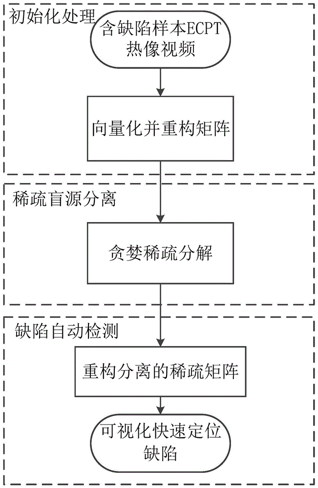
The invention discloses a greedy sparse decomposition-based ECPT defect rapid detection method, and by use of the formation of temperature concentrated areas and spatial distribution sparse characteristics of both ends of a crack and a gap, a thermograph video space is processed by innovated statistical signal processing algorithm, namely greedy sparse decomposition for automatic and direct separation of defect thermal model components without analysis of other specific thermal model blind source region for realization of ECPT defect automatic rapid detection and quantification. By combining ECPT nondestructive testing physical principle, a single channel blind source separation model is constructed, by combination of sparse analysis theory, the greedy sparse decomposition-based ECPT defect rapid detection method can be used for conductor material defect automatic rapid detection, the greedy sparse decomposition-based ECPT defect rapid detection method can directly handle an ECPT thermograph video without artificial selection of thermograph or pixel features, and the loss of large amount of data is avoided. At the same time, no additional signal processing method is added and defects can be automatically, accurately and rapidly detected.

Description

technical field [0001] The invention belongs to the technical field of non-destructive testing, and more specifically relates to a fast defect detection method of ECPT (Eddy Current Pulsed Thermography, eddy current pulsed thermography) based on greedy sparse decomposition. Background technique [0002] Non-destructive testing technology is an important means to control product quality and ensure the safe operation of in-service equipment. Eddy current pulsed thermal imaging (ECPT) combines eddy current and thermal imaging technology to realize rapid detection of defects at different depths in a wide range. [0003] At present, ECPT’s detection and characterization of conductor material defects is still limited to the artificial selection of frame images recorded by thermal imaging cameras to identify and locate defects. This type of processing will lose a lot of data information, and cause inaccurate defect detection and positioning, and even wrongly determine defects. qua...

Claims


Application Information

Patent Timeline
IPC IPC(8): G01N25/72
Inventor 高斌田贵云
Owner UNIV OF ELECTRONIC SCI & TECH OF CHINA
Learn More