Linear array SAR backward projection self-focusing imaging method based on positive semi-definite programming

A technique of semi-positive definite planning and imaging method, used in radio wave measurement systems, reflection/re-radiation of radio waves, utilization of re-radiation, etc.

Inactive Publication Date: 2015-08-12
UNIV OF ELECTRONIC SCI & TECH OF CHINA
View PDF2 Cites 25 Cited by
  • Summary
  • Abstract
  • Description
  • Claims
  • Application Information

AI Technical Summary

Problems solved by technology

As far as I know, there is no linear array SAR backprojection self-

Method used


Image

  • Linear array SAR backward projection self-focusing imaging method based on positive semi-definite programming
  • Linear array SAR backward projection self-focusing imaging method based on positive semi-definite programming
  • Linear array SAR backward projection self-focusing imaging method based on positive semi-definite programming

Examples


Embodiment Construction

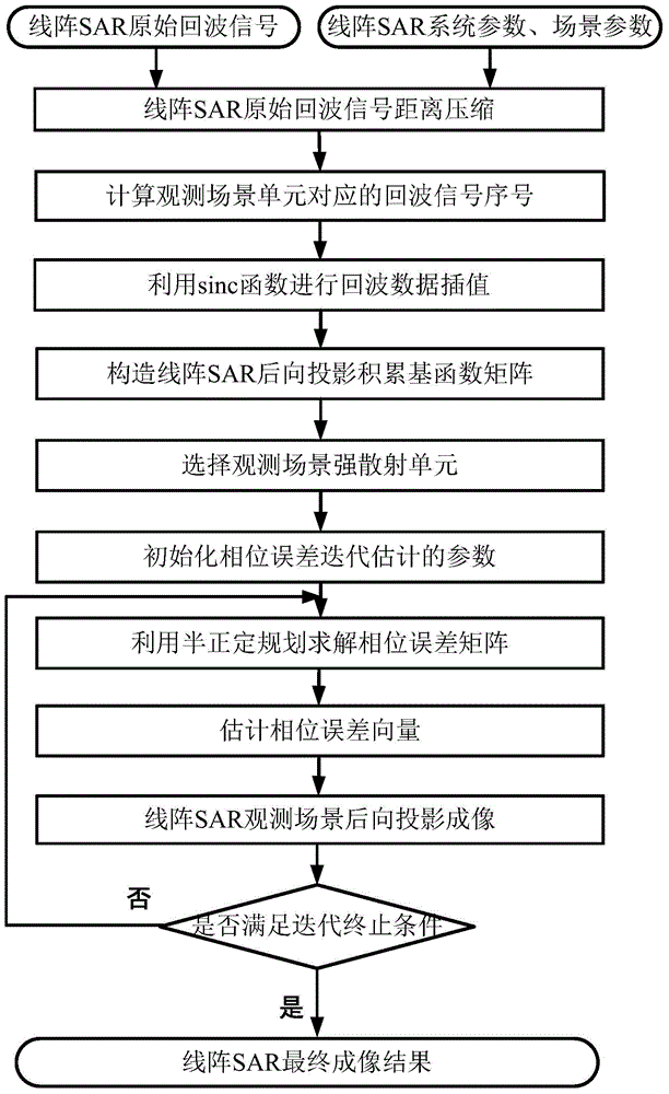
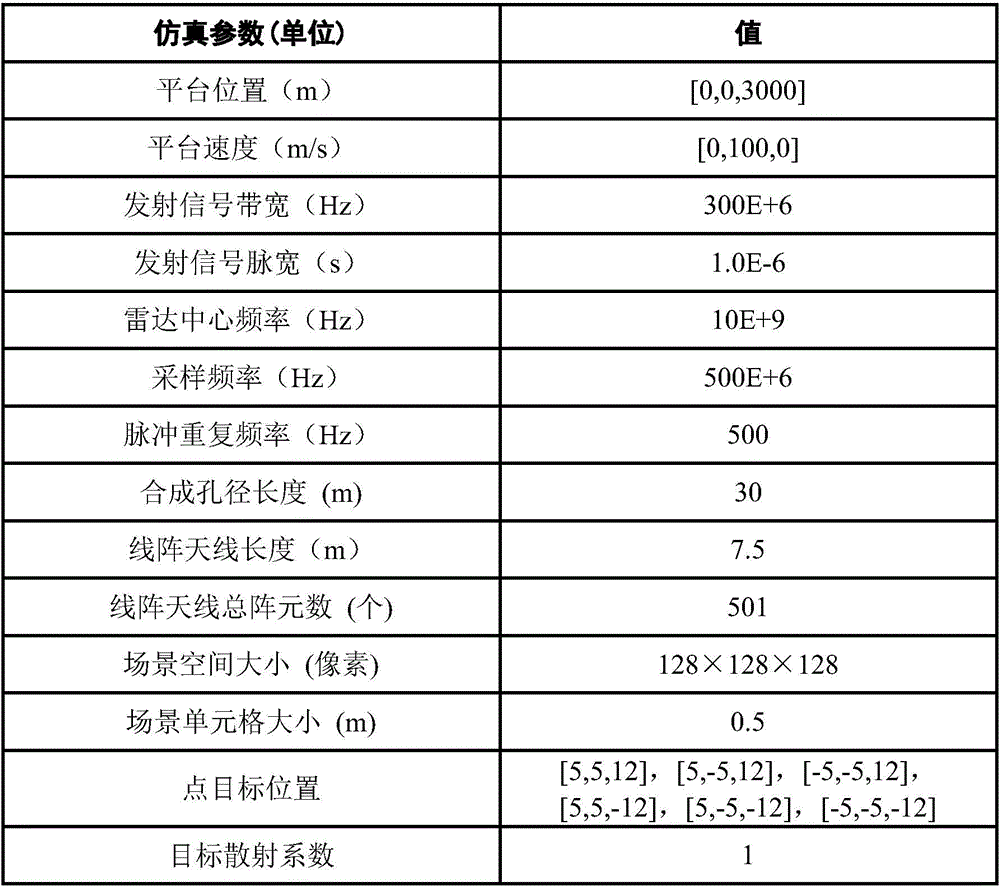
[0080] The present invention mainly adopts the method of simulation experiment to verify, and all steps and conclusions are verified on MATLABR2008b. The specific implementation steps are as follows:

[0081] Step 1. Initialize the linear array SAR system parameters and echo data:

[0082] Initialize the linear array SAR system parameters include: platform velocity vector V=[0,100,0]m / s, platform velocity v x =0m / s, the velocity v of the platform on the longitudinal axis of the horizontal plane y =100m / s, the upward velocity v of the platform at the vertical height of the ground z =0m / s; the initial position vector P of each array element of the linear array antenna n (0)=[0.015·(n-251),0,3000]m, where n is the serial number of the antenna array element, which is a natural number, n=1,2,...,N, N is the array element of the linear array antenna The total number and N=501, the initial position x of the nth antenna element on the horizontal axis n (0)=0.015·(n-251)m, the ini...


PUM


Abstract

The invention discloses a linear array SAR backward projection self-focusing imaging method based on positive semi-definite programming. A primary function matrix is accumulated through constructing a linear array SAR backward projection. A positive semi-definite programming method in a convex optimization theory is used for estimating a phase error matrix in linear array SAR echo data. A minimum rank of a product matrix between a backward projection accumulated primary function matrix and the phase error matrix is used. An optimal matrix under a constraining condition is solved for realizing phase error estimation of the linear array SAR and self-focusing imaging, thereby converting the linear array SAR backward projection algorithm imaging process to a form of multiplexing matrix with a vector, and obtaining a linear array SAR imaging result.

Description

Technical field: [0001] The technical invention belongs to the technical field of radar, and in particular relates to the technical field of synthetic aperture radar (SAR) imaging. Background technique: [0002] Traditional Synthetic Aperture Radar (SAR) uses the linear motion of a single antenna to synthesize a one-dimensional virtual linear array antenna to obtain high resolution in the azimuth direction, and then uses pulse compression technology to obtain high resolution in the radar line of sight direction, thereby realizing two-dimensional imaging of the observation scene . However, the traditional 2D SAR mainly works in the side-view imaging mode, and there are terrain occlusion, shadow effects and top-bottom inversion problems in the side-view imaging, so the traditional 2D SAR cannot obtain satisfactory results in complex undulating terrain such as cities, mountains and canyons. Imaging results. The basic principle of 3D SAR is to synthesize a virtual two-dimensio...

Claims


Application Information

Patent Timeline
IPC IPC(8): G01S13/90
CPCG01S13/904G01S13/9017G01S13/9019
Inventor 韦顺军张晓玲吴文俊刘嘉宁
Owner UNIV OF ELECTRONIC SCI & TECH OF CHINA
Why Eureka
Try Eureka