
Binary coded symbol modulation method based on time domain raised cosine pulse

A time-domain raised cosine and binary coding technology, which is applied in the field of satellite navigation system signals, can solve the problems of autocorrelation function, code tracking performance, anti-multipath and anti-interference ability, and power amplifier efficiency reduction.

Inactive Publication Date: 2015-08-12
HARBIN ENG UNIV
View PDF5 Cites 6 Cited by
  • Summary
  • Abstract
  • Description
  • Claims
  • Application Information

AI Technical Summary

Problems solved by technology

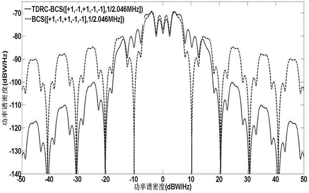
The BCS modulation method given in the article will bring large-scale sidelobes outside the band to reduce the efficiency of the power amplifier, and the autocorrelation function, code tracking performance, anti-multipath and anti-interference ability of the signal are still not ideal, so the present invention proposes a A binary-coded symbol modulation method based on time-domain raised cosine pulses, which can effectively reduce the large-scale sidelobes of the power spectrum, reduce the interference to adjacent signals, improve the power efficiency of navigation signals, and have better code tracking performance , anti-multipath and anti-interference ability, and has good autocorrelation characteristics at the same time, which greatly reduces the difficulty of signal acquisition and tracking, and provides a new choice for the signal waveform design of my country's future Compass satellite navigation system

Method used


Image

  • Binary coded symbol modulation method based on time domain raised cosine pulse
  • Binary coded symbol modulation method based on time domain raised cosine pulse
  • Binary coded symbol modulation method based on time domain raised cosine pulse

Examples


Embodiment Construction

[0034] The present invention will be further described below in conjunction with accompanying drawing:

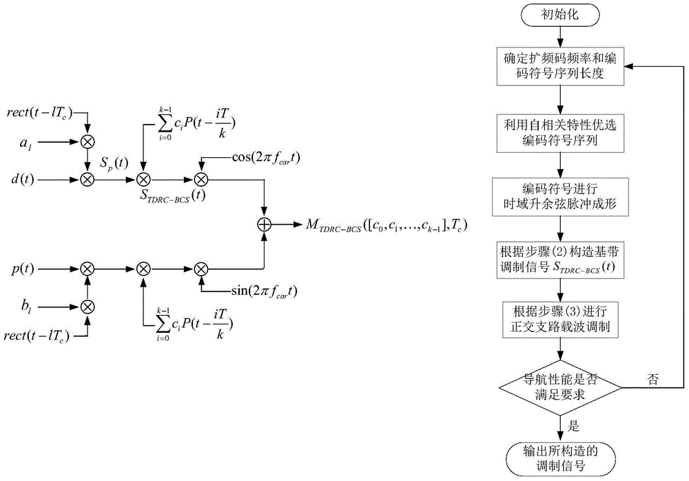
[0035] The present invention proposes a binary coded symbol modulation method based on time-domain raised cosine pulses, so that the navigation signal has better code tracking performance, anti-interference, anti-multipath and compatibility with other system signals, and effectively suppresses large power spectrum The sidelobe of the amplitude improves the power efficiency of the navigation signal, has good autocorrelation characteristics, provides more accurate acquisition and tracking performance, and has both the signal constant envelope characteristic, which provides the signal waveform design for the future Compass satellite navigation system in my country. a new option.

[0036] Its implementation process is as follows: first determine the frequency f of the spreading code c or period T c and the coded symbol sequence length k, the coded symbol sequence [c 0 ,c 1 ,....


PUM


Abstract

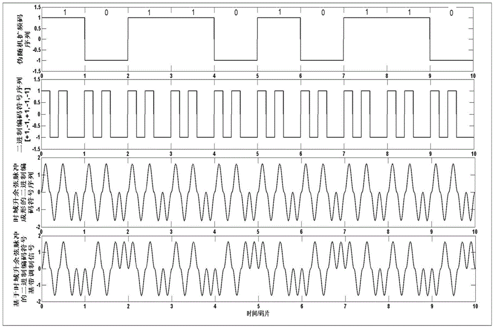
The present invention belongs to the field of satellite navigation system signal, and especially relates to a binary coded symbol modulation method based on a time domain raised cosine pulse. The binary coded symbol modulation method comprises the steps of: first determining the frequency and period of a spreading code and the length of a coded symbol sequence, and selecting the optimal coded symbol sequence through a signal auto-correlation characteristic; performing spread spectrum for a navigation signal by using a pseudo random sequence according to the determined frequency or period of the spreading code and the optimal coded symbol sequence, so as to obtain a spread spectrum signal; performing carrier modulation of an orthogonal branch for an obtained binary coded symbol base-band modulation signal based on a time domain raised cosine pulse, so as to obtain a binary coded symbol modulation signal based on the time domain raised cosine pulse; and re-determining the frequency or period of the spreading code and the length of the coded symbol sequence, and selecting the optimal coded symbol sequence. Compared with a traditional BCS modulation, the modulation signal obtained by the binary coded symbol modulation method of the present invention is faster in power spectrum sidelobe attenuation speed and lower in amplitude, and is higher in energy concentration degree.

Description

technical field [0001] The invention belongs to the field of satellite navigation system signals, and in particular relates to a binary coded symbol modulation method based on time-domain raised cosine pulses. Background technique [0002] The navigation modulation signal waveform is a key link in the design of the navigation signal system. The signal waveform affects the performance of the navigation system by affecting the autocorrelation function and power spectrum of the navigation signal. With the continuous development of the four global navigation satellite systems (Global Navigation Satellite System, GNSS) of the United States GPS, Russia GLONASS, EU Galileo, and China Combass, and regional navigation systems such as Japan's QZSS and India's IRNSS, it is estimated that by 2030, there will be more than 160 navigation satellites. In order to enable multiple signals to better share the limited frequency band of the Global Navigation Satellite System (GNSS), and to furth...

Claims


Application Information

Patent Timeline
Patent Type & Authority Applications(China)
IPC IPC(8): G01S19/35G01S19/30
CPCG01S19/35G01S19/30
Inventor 薛睿孙岩博赵旦峰曹庆铭
Owner HARBIN ENG UNIV
Learn More