Double-camera module group

A dual-camera and lens module technology, applied in image communication, TV, color TV, etc., can solve the problems of reducing the quality of image shooting, achieve the effects of improving picture quality, solving inconsistent motion, and avoiding magnetic interference

Active Publication Date: 2015-08-12
NANCHANG OFILM JINGRUN TECH CO LTD
4 Cites 46 Cited by

AI-Extracted Technical Summary

Problems solved by technology

[0004] However, when the dual camera module with the above structure is adopted, the voice coil motors i...

Method used

Two lens modules 400 are installed on the same mirror base 200, and a liquid crystal lens 500 is set on the top surface 220 of the mirror base 200, so that it covers the two lens modules 400, the welding lead in the mirror base 200 The pin 600 can electrically connect the liquid crystal lens 500 with the circuit board 100. During the assembly process, the lens module 400 has been adjusted to focus. Power supply, correspondingly change the optical path of light passing through the liquid crystal lens 500 at different voltages, and realize the focusing function without the need for a voice coil motor, so it can effectively avoid magnetic interference between the two voice coil motors, thereby improving the picture quality. Moreover, the focusing function of the two lens modules 400 is realized through a liquid crystal lens 500, so it can also effectively solve the problem of inconsistency of mo...

Abstract

The invention relates to a double-camera module group, and the module group comprises a circuit board, a lens seat, two image sensors, two lens module groups, a liquid crystal lens, and a welding pin. The two lens module groups are disposed on the same lens seat, and the bottom surface of the lens seat is connected with the circuit board. Moreover, the top surface of the lens seat is provided with the liquid crystal lens, thereby enabling the liquid crystal lens to cover the two lens module groups. The welding pin in the lens seat can enable the liquid crystal lens to be electrically connected with the circuit board. During assembly, the focuses of the lens module groups are adjusted, and the liquid crystal lens is used for focusing during photographing. In other words, the circuit board supplies power to the liquid crystal lens through the welding pin. The path of light passing through the liquid crystal lens is correspondingly changed during different voltages, and the focusing function is achieved under the condition of no voice coil motor. Therefore, the module group can effectively prevent the magnetic interference between two voice coil motors, and improves the image quality. Moreover, the two lens module groups achieve the focusing function through the liquid crystal lens, so the module group can effectively solve a problem that the movement of the two lens module groups is not consistent, and improves the image quality.

Application Domain

Technology Topic

Image

  • Double-camera module group
  • Double-camera module group
  • Double-camera module group

Examples

  • Experimental program(1)

Example Embodiment

[0027] In order to make the above-mentioned objects, features and advantages of the present invention more obvious and understandable, the specific embodiments of the present invention will be described in detail below with reference to the accompanying drawings. In the following description, many specific details are explained in order to fully understand the present invention. However, the present invention can be implemented in many other ways different from those described herein, and those skilled in the art can make similar improvements without departing from the connotation of the present invention. Therefore, the present invention is not limited by the specific implementation disclosed below.
[0028] The terms "vertical", "horizontal", "left", "right" and similar expressions used herein are for illustrative purposes only, and do not mean the only implementation.
[0029] Unless otherwise defined, all technical and scientific terms used herein have the same meaning as commonly understood by those skilled in the technical field of the present invention. The terminology used in the specification of the present invention herein is only for the purpose of describing specific embodiments, and is not intended to limit the present invention. The term "and/or" as used herein includes any and all combinations of one or more related listed items.
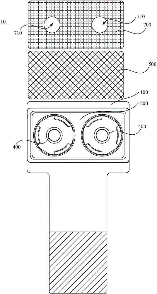
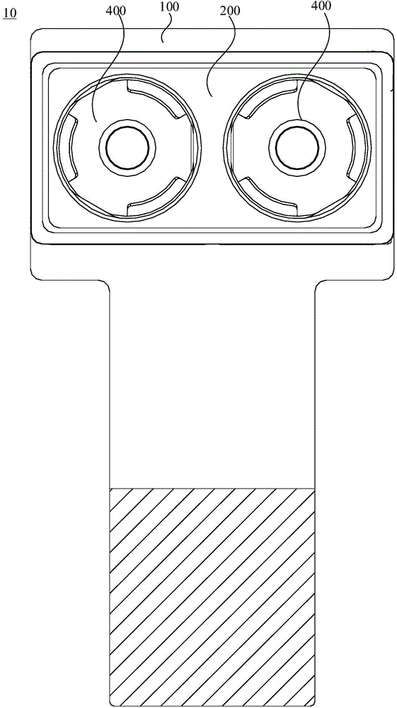
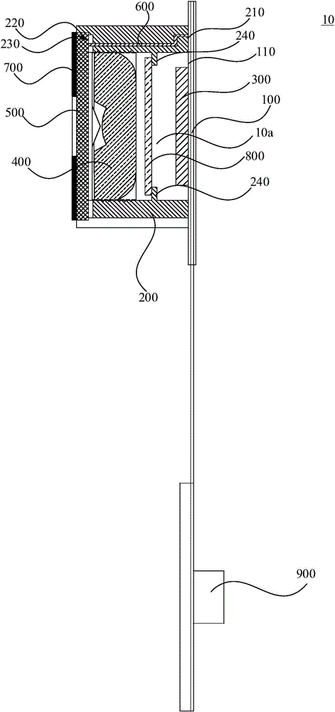
[0030] See Figure 1 to Figure 3 , Is a dual camera module 10 in an embodiment. The dual camera module 10 can also achieve a focusing function without a voice coil motor. The dual camera module 10 includes a circuit board 100, a lens holder 200, two image sensors 300, two lens modules 400, a liquid crystal lens 500, welding pins 600, a light shield 700 and a filter 800.
[0031] The circuit board 100 includes a mounting surface 110. The circuit board 100 may be a flexible circuit board or a printed circuit board or the like. When it is a flexible circuit board, a reinforcing plate can also be provided to increase the strength of the flexible circuit board.
[0032] The lens holder 200 includes a bottom surface 210 and a top surface 220, and the bottom surface 210 is disposed on the mounting surface 110. Two through holes (not shown in the figure) are formed on the lens holder 200 to penetrate the bottom surface 210 and the top surface 220 (not shown in the figure), and the two through holes (not shown in the figure) are arranged at intervals. The lens holder 200 is an integrated lens holder. Therefore, the volume can be reduced to meet the development needs of miniaturization and portability.
[0033] The two image sensors 300 are both disposed on the mounting surface 110 and are electrically connected to the circuit board 100. The image sensor 300 may be a CCD (Charge Coupled Device) or a CMOS (Complementary Metal-Oxide Semiconductor). The two image sensors 300 are arranged at intervals. The image sensor 300 is used to convert captured picture information into electrical signals.
[0034] Among the two lens modules 400, one lens module 400 is correspondingly received in a through hole, and the periphery of the lens module 400 is disposed on the side wall of the through hole. Specifically, the lens module 400 includes a lens barrel and a lens arranged in the lens barrel. The outer periphery of the lens barrel is provided with threads, the inner side wall of the through hole is provided with threads, and the lens barrel is screwed on the inner side wall of the through hole through the threads. The lens can be a plastic lens. The number of lenses can be two or more.
[0035] The liquid crystal lens 500 is disposed on the top surface 220 of the lens holder 200, and the liquid crystal lens 500 covers two through holes. The liquid crystal lens 500, the lens holder 200 and the circuit board 100 together form two sealed and spaced receiving cavities 10a, and an image sensor 300 is correspondingly received in a receiving cavity 10a. The top surface 220 of the lens holder 200 is recessed toward the bottom surface 210 of the lens holder 200 to form a groove 230. The liquid crystal lens 500 is arranged in the groove 230. The groove 230 is used to carry the liquid crystal lens 500. The side wall of the groove 230 It is beneficial to prevent the liquid crystal lens 500 from moving, and facilitates the alignment of the liquid crystal lens 500 during installation. The side of the liquid crystal lens 500 away from the circuit board 100 is flush with the top surface 220 of the lens holder 200.
[0036] The soldering pin 600 is arranged on the side wall of the through hole, and one end is electrically connected to the circuit board 100 and the other end is electrically connected to the liquid crystal lens 500. The soldering pin 600 is arranged on the side wall of one of the through holes and used for electrically connecting the liquid crystal lens 500 and the circuit board 100. The circuit board 100 supplies power to the liquid crystal lens 500 through the soldering pins 600, and correspondingly changes the optical path of the light passing through the liquid crystal lens 500 at different voltages to realize the focusing function. Therefore, there is no need for mechanical moving lenses, precise focusing and fast response speed, and low power consumption.
[0037] The shading sheet 700 is arranged on the surface of the liquid crystal lens 500 facing away from the circuit board 100. The shading sheet 700 is provided with two light-transmitting holes 710. One light-transmitting hole 710 corresponds to a lens module 400 to prevent stray light from entering the lens module. 400, affecting the image quality. The shading sheet 700 may be a black shading sheet 700.
[0038] The filter 800 is received in the through hole and located between the lens module 400 and the image sensor 300. The filter 800 is an infrared cut-off filter 800, which is used to filter infrared light and avoid image distortion. Specifically, a protrusion 240 is formed protruding inward from the side wall of each through hole, and the filter 800 is disposed on the protrusion 240.
[0039] Specifically, in this embodiment, the connector 900 is further included. The connector 900 is disposed at the extension end of the circuit board 100 and is used to transmit the signal of the image sensor 300.
[0040] The aforementioned dual camera module 10 has at least the following advantages:
[0041] Two lens modules 400 are installed on the same lens holder 200, and a liquid crystal lens 500 is arranged on the top surface 220 of the lens holder 200 to cover the two lens modules 400. The welding pins 600 in the lens holder 200 can be The liquid crystal lens 500 is electrically connected to the circuit board 100. During the assembly process, the lens module 400 has been adjusted to focus. When taking pictures, the liquid crystal lens 500 is used for focusing, that is, the circuit board 100 supplies power to the liquid crystal lens 500 through the soldering pins 600. At different voltages, the light path of the light passing through the liquid crystal lens 500 is changed correspondingly, and the focusing function is realized without the voice coil motor. Therefore, the magnetic interference between the two voice coil motors can be effectively avoided, thereby improving the picture quality. Moreover, the two lens modules 400 realize the focusing function through a liquid crystal lens 500, so the problem of inconsistent motion when the two conventional two voice coil motors drive the two lens modules 400 separately can also be effectively solved, and the picture accuracy can be improved.
[0042] The above-mentioned embodiments only express several implementation modes of the present invention, and their description is more specific and detailed, but they should not be interpreted as a limitation on the patent scope of the present invention. It should be pointed out that for those of ordinary skill in the art, without departing from the concept of the present invention, several modifications and improvements can be made, and these all fall within the protection scope of the present invention. Therefore, the protection scope of the patent of the present invention should be subject to the appended claims.

PUM

no PUM

Description & Claims & Application Information

We can also present the details of the Description, Claims and Application information to help users get a comprehensive understanding of the technical details of the patent, such as background art, summary of invention, brief description of drawings, description of embodiments, and other original content. On the other hand, users can also determine the specific scope of protection of the technology through the list of claims; as well as understand the changes in the life cycle of the technology with the presentation of the patent timeline. Login to view more.

Similar technology patents

Non-magnetic heating temperature control system

InactiveCN103576721AAvoid Magnetic InterferenceFast heatingTemperatue controlMagnetic noiseControl system
Owner:HARBIN ENG UNIV

Multi-lens module structure and electronic device

InactiveCN112188044AAvoid magnetic interferenceShorten the separation distanceTelevision system detailsColor television detailsBoth lensesMechanical engineering
Owner:TRIPLE WIN TECHSHENZHEN CO LTD

Real-time error correction device for computer application software

InactiveCN111913533AAvoid Magnetic InterferenceImprove signal strength and transfer rateDigital processing power distributionComputer caseApplication software
Owner:LAIWU VOCATIONAL & TECHNICAL COLLEGE

Classification and recommendation of technical efficacy words

  • Improve picture quality
  • Avoid Magnetic Interference

Video coding method and device

ActiveCN106162177AImprove picture qualityReduce occupancyDigital video signal modificationNon region of interestVideo encoding
Owner:TENCENT TECH (SHENZHEN) CO LTD

Non-magnetic heating temperature control system

InactiveCN103576721AAvoid Magnetic InterferenceFast heatingTemperatue controlMagnetic noiseControl system
Owner:HARBIN ENG UNIV

Real-time error correction device for computer application software

InactiveCN111913533AAvoid Magnetic InterferenceImprove signal strength and transfer rateDigital processing power distributionComputer caseApplication software
Owner:LAIWU VOCATIONAL & TECHNICAL COLLEGE

Multi-lens module structure and electronic device

InactiveCN112188044AAvoid magnetic interferenceShorten the separation distanceTelevision system detailsColor television detailsBoth lensesMechanical engineering
Owner:TRIPLE WIN TECHSHENZHEN CO LTD
Why Eureka
Try Eureka