
Method for producing rare-earth magnet

一种制造方法、稀土的技术,应用在电感/变压器/磁铁制造、磁性物体、磁性材料等方向,能够解决矫顽力性能降低、晶界相率降低、没有公开解决等问题,达到矫顽力性能高的效果

Active Publication Date: 2015-08-12
TOYOTA JIDOSHA KK
View PDF7 Cites 15 Cited by
  • Summary
  • Abstract
  • Description
  • Claims
  • Application Information

AI Technical Summary

Problems solved by technology

[0008] However, in order to increase the magnetization of rare earth magnets, attempts have been made to increase the main phase ratio (for example, to make the main phase ratio about 95% or more), but the increase in the main phase ratio conversely reduces the grain boundary phase ratio.
Therefore, when the modified alloy is diffused at the grain boundary, the molten modified alloy cannot sufficiently penetrate into the inside of the rare-earth magnet, and although the magnetization is improved, the coercive force performance is lowered.
[0009] For example, the above-mentioned problem is not proposed in Patent Document 1, so the means for solving this problem are not disclosed.

Method used


Image

  • Method for producing rare-earth magnet
  • Method for producing rare-earth magnet
  • Method for producing rare-earth magnet

Examples


Embodiment Construction

[0046] (Method for manufacturing rare earth magnets)

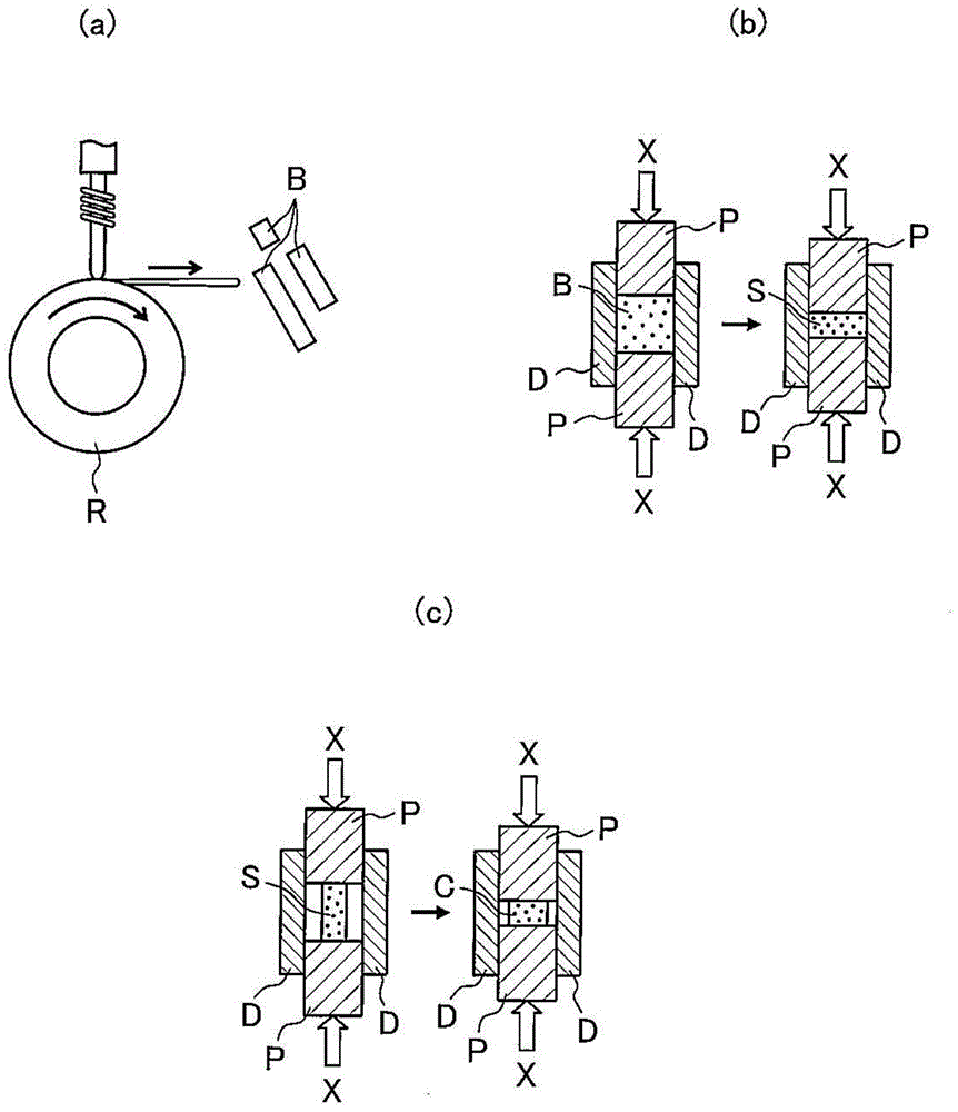
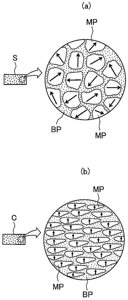
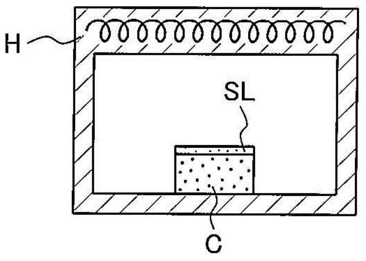
[0047] figure 1 (a), figure 1 (b) is a schematic diagram illustrating the first step of the manufacturing method of the rare earth magnet of the present invention in this order, figure 1 (c) is a schematic diagram explaining the second step. In addition, image 3 It is a schematic diagram explaining the third step of the method of manufacturing the rare earth magnet of the present invention. In addition, figure 2 (a) is stated in figure 1 (b) A picture of the microstructure of the sintered body shown in, figure 2 (b) is the description figure 1 (c) A diagram of the microstructure of the rare earth magnet precursor. In addition, Figure 4 It is a diagram showing the microstructure of the crystal structure of the manufactured rare earth magnet, Figure 5 Is to Figure 4 The main phase and the grain boundary phase in the image are further enlarged.

[0048] Such as figure 1 (a) As shown in (a), in a furnace not shown in an Ar g...


PUM

PropertyMeasurementUnit
particle diameteraaaaaaaaaa

Abstract

The present invention is a method capable of producing a rare-earth magnet with excellent magnetization and coercivity. The method includes producing a sintered body including a main phase and grain boundary phase and represented by (R1 1-x R2 x ) a TM b B c M d (where R1 represents one or more rare-earth elements including Y, R2 represents a rare-earth element different than R1, TM represents transition metal including at least one of Fe, Ni, or Co, B represents boron, M represents at least one of Ti, Ga, Zn, Si, Al,etc., 0.01 ‰¤ x ‰¤ 1, 12 ‰¤ a ‰¤ 20, b = 100 - a - c - d, 5 ‰¤ c ‰¤ 20, and 0 ‰¤ d ‰¤ 3 (all at%)); applying hot deformation processing to the sintered body to produce a precursor of the magnet; and diffusing / infiltrating melt of a R3-M modifying alloy (rare-earth element where R3 includes R1 and R2) into the grain boundary phase of the precursor.

Description

Technical field [0001] The present invention relates to a method for manufacturing rare earth magnets. Background technique [0002] Rare-earth magnets using rare-earth elements are also called permanent magnets, and are used in motors for driving hybrid vehicles and electric cars, etc., in addition to motors that constitute hard disks and MRIs. [0003] As an index of the magnet performance of the rare earth magnet, residual magnetization (residual magnetic flux density) and coercive force can be cited. However, compared with the increase in the amount of heat generated by the miniaturization and high current density of the motor, the The heat resistance requirements of the rare earth magnets used have also been further improved, and how to maintain the coercivity of the magnets under high-temperature use has become one of the important research topics in this technical field. [0004] Enumerating Nd-Fe-B magnets, which are one of the rare earth magnets that are mostly used in moto...

Claims


Application Information

Patent Timeline
Patent Type & Authority Applications(China)
IPC IPC(8): H01F41/02H01F1/053
CPCB22F3/24H01F41/0293H01F1/0577B22F3/26H01F1/0557C22C38/005B22F3/10H01F41/0266C22C38/002C22C38/10C22C38/001C22C33/025C22C33/0257B22F2009/048B22F2998/10B22F2999/00C22C2202/02B22F1/07B22F3/02H01F41/005
Inventor 佐久间纪次庄司哲也芳贺一昭
Owner TOYOTA JIDOSHA KK
Learn More