Slow rising edge pulse signal identification circuit

A technology of pulse signal and identification circuit, applied in the direction of pulse description, etc., can solve the problems of low sensitivity, complex constant ratio timing circuit, easy false triggering, etc., and achieve the effect of high detection sensitivity, simple identification method and circuit form.

Active Publication Date: 2015-08-12
BEIJING INST OF CONTROL ENG
View PDF6 Cites 10 Cited by
  • Summary
  • Abstract
  • Description
  • Claims
  • Application Information

AI Technical Summary

Problems solved by technology

[0004] The double constant ratio timing method uses two constant ratio timing circuits with different thresholds to judge the speed of the rising edge of the pulse. The constant ratio timing circuit is complex and consumes a lot of power;
[0005] The combination method of leading edge timing and constant ratio timing uses the timing relationship between leading edge timing and constant ratio timing t

Method used


Image

  • Slow rising edge pulse signal identification circuit
  • Slow rising edge pulse signal identification circuit
  • Slow rising edge pulse signal identification circuit

Examples


Embodiment Construction

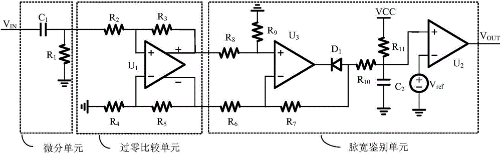
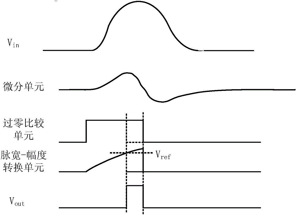
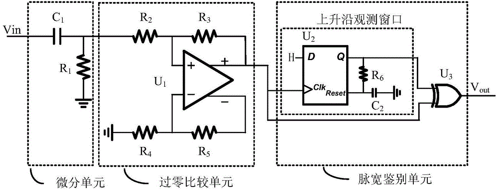
[0026] The discriminating circuit of the slow rising edge pulse signal of the present invention includes three parts: a differential unit, a zero-crossing comparison unit and a pulse width discriminating unit. Wherein, the differentiation unit is used to extract the rising edge of the input photon pulse, and convert the input unipolar photon pulse signal into a bipolar signal after differentiating. The selection of the differential time constant should maximize the signal-to-noise ratio of the bipolar signal. The zero-crossing comparison unit converts the bipolar signal into a digital pulse signal with a certain pulse width according to the set comparison threshold. The threshold of the comparison unit is determined by the definition of the slow rising edge signal (that is, what kind of signal needs to be detected). The pulse width identification unit judges whether the width of the digital pulse signal exceeds the set threshold value, wherein the threshold value is determine...


PUM


Abstract

The invention relates to a slow rising edge pulse signal identification circuit. The slow rising edge pulse signal identification circuit includes a differential unit, a zero crossing comparison unit and a pulse width identification unit; the differential unit performs differential processing on unipolar photon pulse signals inputted from the outside, so that bipolar signals with two zero crossing points can be formed and transmitted to the zero crossing comparison unit; the zero crossing comparison unit converts the bipolar signals into digital pulse signals with a certain pulse width according to a set comparison threshold value, and transmits the digital pulse signals to the pulse width identification unit; and the pulse width identification unit judges whether the width of the digital pulse signals exceeds a set identification threshold value, and judges that the photon pulse signals inputted from the outside are slow rising edge signals and outputs a high-electric level pulse if the width of the digital pulse signals exceeds the set identification threshold value, otherwise, outputs a low-electric level pulse. The slow rising edge pulse signal identification circuit of the invention has the advantages of simple circuit form and high sensitivity.

Description

technical field [0001] The invention relates to a pulse signal detection circuit. Background technique [0002] The X-ray pulsar navigation sensor is one of the keys to realize X-ray pulsar navigation, and it is required to realize large-area and high-sensitivity detection of X-ray pulsar radiation signals. In the space radiation environment, high-energy particles interact with satellite and telescope materials, and the detectors will receive high-energy particles and their secondary excited particles. It is difficult to capture only a few celestial source radiation in the complex X-ray background. Signal. For this reason, reducing the background of the telescope is the basic requirement for realizing high-sensitivity astronomical observation. Background, the main sources include the cosmic X-ray radiation background, particles captured by the geomagnetic field, and the earth's reflection. Since the rising edge of the signal output by the interaction between high-energy p...

Claims


Application Information

Patent Timeline
IPC IPC(8): H03K5/125
Inventor 陈建武梅志武莫亚男吕政欣邓楼楼史永敏
Owner BEIJING INST OF CONTROL ENG
Why Eureka
Try Eureka