
Coverage Hole Repair Method and System for Failure Nodes in Internet of Things

A technology that covers holes and failed nodes, applied in network topology, advanced technology, electrical components, etc., can solve problems that are not suitable for large-scale applications, affect the quality of service in the monitoring area, increase node costs, etc., to prolong the network survival time, good The effect of network coverage quality and guaranteed communication quality

Inactive Publication Date: 2018-05-15
NANCHANG UNIV +1
View PDF4 Cites 1 Cited by
  • Summary
  • Abstract
  • Description
  • Claims
  • Application Information

AI Technical Summary

Problems solved by technology

The network coverage seriously affects the quality of service in the monitoring area
During the operation of the network, two important issues need to be considered: one is the network connectivity of the sensor nodes after deployment, and the other is the energy efficiency of the sensor nodes.
[0006] Multiple coverage of the entire network can solve the quality of network coverage, but in the wide-area Internet of Things, multiple sensor nodes cover a target object at the same time, which will increase the node cost and is not suitable for large-area applications
In addition, in the process of clustering and repairing coverage holes in traditional sensor networks, the real-time residual energy of sensor nodes is not considered.
Therefore, the lifetime of the network cannot be guaranteed after the repair

Method used


Image

  • Coverage Hole Repair Method and System for Failure Nodes in Internet of Things
  • Coverage Hole Repair Method and System for Failure Nodes in Internet of Things
  • Coverage Hole Repair Method and System for Failure Nodes in Internet of Things

Examples


Embodiment Construction

[0045] The implementation process of the present invention will be described in detail below in conjunction with the accompanying drawings and specific embodiments.

[0046] The hybrid sensor network includes static sensor nodes responsible for sensing events and redundant sensor nodes with mobile capabilities that can be used for scheduling. The two coordinate with each other to complete the deployment of the network. Both are identical in terms of communication, computing power and the amount of energy they carry. During the initial deployment, the network is fully covered by all static sensor nodes, and other redundant sensor nodes are deployed in the area covered by the designated static nodes in a partially redundant coverage manner. After normal operation, the static sensor node is responsible for sensing data, while the redundant sensor node only exchanges residual energy information with the static sensor node where it is located, and is not responsible for sensing dat...


PUM


Abstract

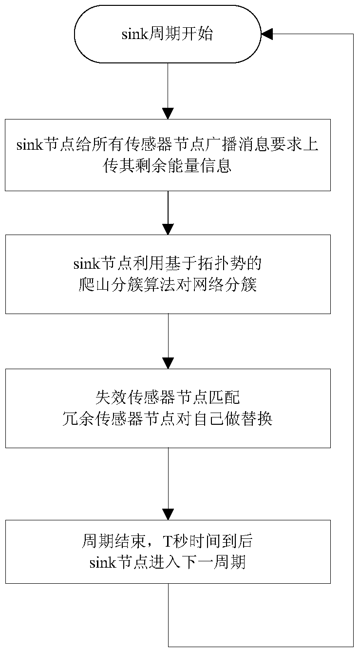
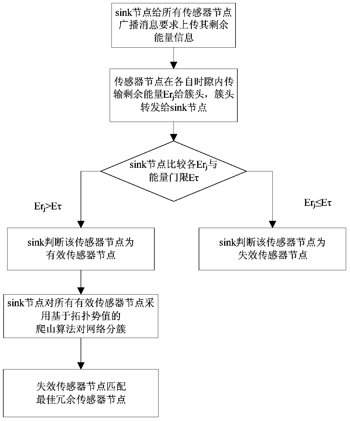
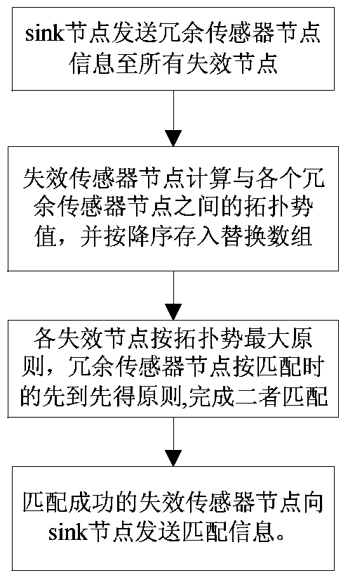
The invention discloses a coverage hole repair method and system for failed nodes in Internet of Things (IOT). The method comprises the steps that a sink node conducts roll poling for remaining energy Erj of all sensor nodes in a network every T seconds; the sink node determines whether each sensor node is effective or not based on preset conditions; the sink node removes an ineffective sensor node based on determination results, and re-clusters the effective sensor nodes in the network according to the remaining energy Erj and the hill climbing algorithm based on topology potential; and the ineffective sensor node calculates the topology potential (img file shown in the description) between the ineffective sensor node and each redundant sensor node, and selecting the matched redundant sensor node to replace the ineffective sensor node according to the maximum topology potential, the principle of first come first served, or a combination of both. According to the invention, the topology potential is used for re-clustering the effective sensor nodes, the optimal redundant sensor node can be selected in accordance with the magnitude of the topology potential and the principle of first come first served, through a combination of the two above, the network is allowed to gain unified energy distribution and always maintain local redundancy coverage in high-density areas of communication, and the network lifetime is extended while the communication quality of the network is ensured.

Description

technical field [0001] The present invention relates to the field of wide-area Internet of Things, and more specifically, to methods for network deployment and repair in the field of wireless sensor networks. Background technique [0002] The Internet of Things refers to the use of radio frequency identification (RFID), infrared sensors and other information sensing devices to connect any item with the Internet in accordance with the agreed agreement, for information exchange and communication, and to realize intelligent identification, positioning, tracking, monitoring and managed network. The Internet of Things consists of perception layer, network layer and application layer. Among them, the perception layer is used to obtain the information of items, including data acquisition equipment such as sensors, sensor networks, etc. The wireless sensor network used for environmental information collection is composed of wireless sensor nodes and access gateways. The wireless n...

Claims


Application Information

Patent Timeline
Patent Type & Authority Patents(China)
IPC IPC(8): H04W24/04H04W40/10
CPCH04W24/04H04W40/10H04W84/18Y02D30/70
Inventor 肖霖焦金宁杨鼎成张天魁周乐
Owner NANCHANG UNIV
Learn More