
Wide angle optical system

Inactive Publication Date: 2013-12-12
MODIEVSKY GREGORY
View PDF7 Cites 0 Cited by
  • Summary
  • Abstract
  • Description
  • Claims
  • Application Information

AI Technical Summary

Benefits of technology

The present invention provides a system that combines a wide FOV lens system with an electromagnetic radiation sensitive device. The lens system diverts wide angle incident wave fronts to parallel wave fronts relative to an axis perpendicular to the lens and the sensitive surface of the device. This way, the signal intercepted by the device is stronger, and a larger amount of incident radiation and more reliable information is processed by the device. The system can transmit, intercept and process modulated electromagnetic radiation at any wavelength range. The technical effect of this invention is to enhance the interaction of incident radiation with the device, resulting in stronger signals and better information processing.

Problems solved by technology

According to current technologies and known art in the field of photovoltaic cells, the main problem remains that the daily arc-like motion of the sun allows for only partial transmittance of radiation to penetrate perfectly oriented solar panels within a limited portion of 50° of the arc (25° for each of east and west directions around the axis of symmetry perpendicular to the solar panel).
The mirror-based technologies are difficult to manufacture and maintain, while the focusing technologies are limited mainly by constraints of focal lengths.

Method used


Image

  • Wide angle optical system
  • Wide angle optical system
  • Wide angle optical system

Examples


Embodiment Construction

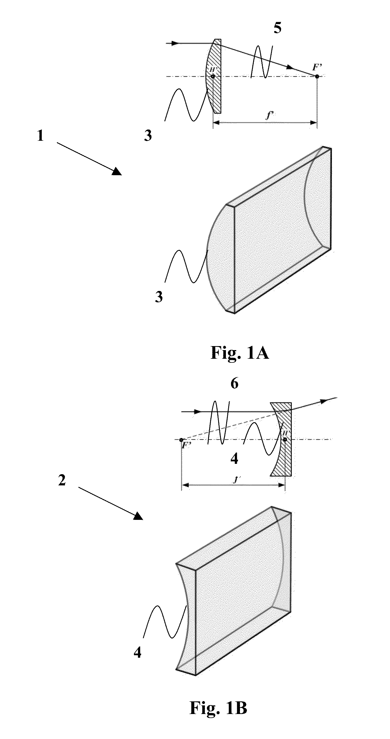
[0062]FIGS. 1A and 1B depict a schematic of convex (1) and concave (2) cylindrical lenses, respectively. The lenses focus light which passes through on to a line instead of on to a point, as a spherical lens would. The curved face or faces (3, 4) of the lenses are sections of a cylinder, and focus the image passing through it onto a line (5, 6) parallel to the intersection of the surface of the lens and a plane tangent to it. The lenses compress the image in the direction perpendicular to this line, and leaves it unaltered in the direction parallel to it (in the tangent plane).

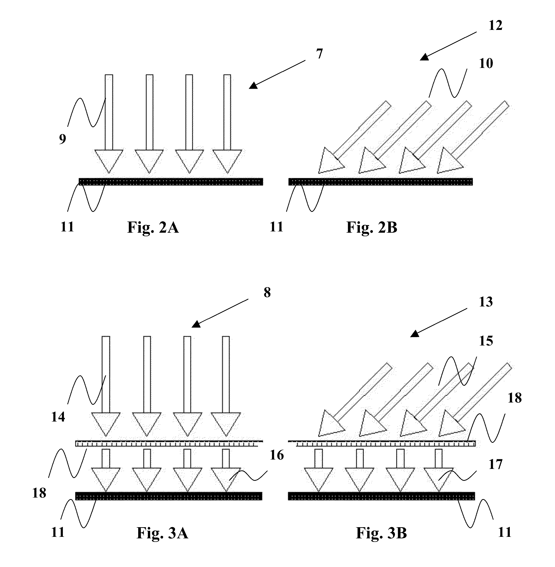
[0063]FIGS. 2A and 3A illustrate a schematic representation (7, 8) of a wave front (9, 14) incident at a perpendicular direction relative to a surface of an electromagnetic radiation sensitive device (11). FIG. 2A illustrates the incidence of the perpendicular wave front (9) directly at the surface of the device (11). In such situation, all the incoming radiation is absorbed and processed by the device without...


PUM


Abstract

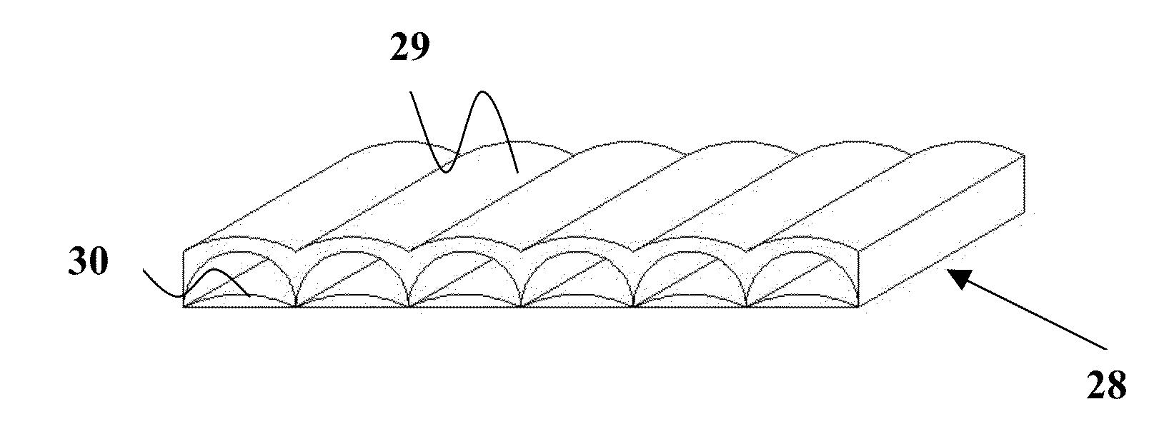
A system for diverting wide angle incident electromagnetic radiation to parallel to an optical axis of a wide FOV lens. The system includes a wide FOV lens system including at least one wide FOV lens and an electromagnetic radiation sensitive device. The wide FOV lens system includes at least one wide FOV lens, the wide FOV lens includes a smooth outer surface that is transparent to the incident electromagnetic radiation. The wide FOV lens system is superposed over an outer surface of the electromagnetic radiation sensitive device, the electromagnetic radiation sensitive device is capable of interacting with the incident electromagnetic radiation.

Description

TECHNICAL FIELD[0001]The present invention pertains to optical systems that complement electromagnetic radiation sensitive devices. In particular, the present invention pertains to optical systems that divert incident electromagnetic radiation from wide FOV (Field Of View) to parallel angle relative to the optical axis of an optical system and perpendicular to an electromagnetic radiation sensitive surface of an electromagnetic radiation sensitive devices.BACKGROUND[0002]The technical problem of loss of wide angle or peripheral incident electromagnetic radiation relative to the perpendicular axis of electromagnetically sensitive devices has been addressed and solved in numerous ways in the prior art. In particular, several solutions were suggested for transmitting or concentrating incident solar radiation at wide angles relative to the axis perpendicular to photovoltaic panels: Fresnel and convex lenses, concentrating mirrors and complex combinations of lenses and mirrors that cause...

Claims


Application Information

Patent Timeline
IPC IPC(8): G01J1/04G01T1/00G01J5/10F24S23/30
CPCY02E10/52G02B3/06H01L31/0543F24S23/31F24S23/30Y02E10/40
Inventor MODIEVSKY, GREGORY
Owner MODIEVSKY GREGORY
Learn More