Composite leaf springs and automotive

A composite material plate and leaf spring technology, which is applied in the direction of leaf springs, springs, vehicle components, etc., can solve the problems affecting the safety performance of the whole vehicle, the difficulty of connecting the composite material leaf spring and metal parts, and the large braking shear force

Active Publication Date: 2017-10-13
BEIQI FOTON MOTOR CO LTD
View PDF6 Cites 0 Cited by
  • Summary
  • Abstract
  • Description
  • Claims
  • Application Information

AI Technical Summary

Problems solved by technology

However, during the braking process of the whole vehicle, the brake shear force borne by the leaf spring is relatively large, and due to the influence of the assembly space of the frame, specifically the limitation of the center distance of the front and rear frame lugs, in the structure It is difficult to connect the composite material leaf spring to the metal parts, which makes the connection method and structural design of the composite material leaf spring and metal parts particularly important. If the structure is unreasonable, during the reliability test of the whole vehicle, The composite leaf spring will be cut off by the metal parts used as roll ears and the bolts used to connect the composite leaf spring, thus destroying the composite leaf spring and affecting the safety performance of the vehicle

Method used


Image

  • Composite leaf springs and automotive
  • Composite leaf springs and automotive
  • Composite leaf springs and automotive

Examples


Embodiment Construction

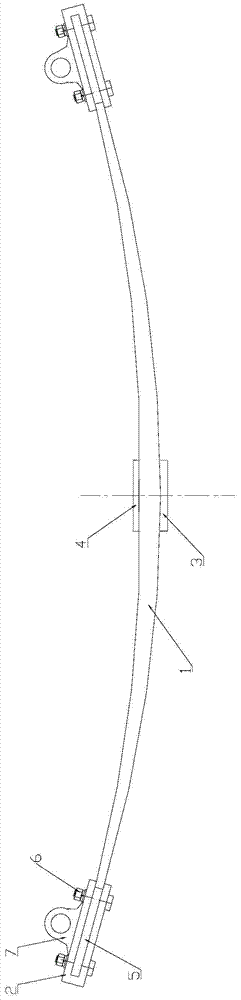
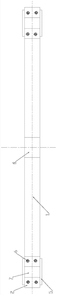
[0023] Specific embodiments of the present invention will be described in detail below in conjunction with the accompanying drawings. It should be understood that the specific embodiments described here are only used to illustrate and explain the present invention, and are not intended to limit the present invention.

[0024] In the description of the present invention, it should be noted that the terms "center", "longitudinal", "transverse", "upper", "lower", "front", "rear", "left", "right", " The orientations or positional relationships indicated by "vertical", "horizontal", "top", "bottom", "inner", "outer", etc. are based on the orientation or positional relationships shown in the drawings, and are only for the convenience of describing the present invention and simplifying Describes, but does not indicate or imply that the device or element referred to must have a specific orientation, be constructed in a specific orientation, and operate in a specific orientation, and t...


PUM


Abstract

The invention relates to the technical field of automobiles, and relates to a composite leaf spring and an automobile. The composite leaf spring includes a bow-shaped leaf spring body and rigid connectors installed at both ends of the leaf spring body. The leaf spring body is formed of fiber-reinforced composite materials; There are grooves on the rigid connector, and the two ends of the leaf spring body are respectively inserted into the grooves; the upper surface of the rigid connector is provided with a boss, and the boss is provided with a mounting for connecting the rigid connector and the frame hanger. The through hole of the pin shaft. Such an arrangement can increase the longitudinal length of the leaf spring body and the contact area between the leaf spring body and the rigid connector while the center distance between the front and rear frame hangers remains unchanged. The rigid connector of the present invention can share the longitudinal force borne by the leaf spring body to a greater extent, and change the action point and direction of force on the leaf spring body during braking, so that the shear force borne by the leaf spring body Reduced, thereby prolonging fatigue life and improving safety performance.

Description

technical field [0001] The invention relates to the technical field of automobiles, in particular to a composite leaf spring and an automobile. Background technique [0002] The current trucks, especially those with two or more rear axles, traditionally use steel leaf springs as a buffer and damping structure, but the steel leaf springs themselves are very heavy, which increases the weight of the vehicle, thereby increasing It increases the fuel consumption rate and has an adverse effect on the handling stability of the vehicle. In addition, steel leaf springs are usually composed of no less than one piece of spring steel, and the inevitable friction between adjacent spring steels will shorten the life of the steel leaf spring. Due to the requirements of large load, low fuel consumption and good handling stability, leaf springs made of composite materials have been widely used. Compared with similar steel leaf springs, composite leaf springs have the characteristics of lig...

Claims


Application Information

Patent Timeline
Patent Type & Authority Patents(China)
IPC IPC(8): B60G11/02B60G11/10
Inventor 赵海龙刘知汉
Owner BEIQI FOTON MOTOR CO LTD
Why Eureka
Try Eureka