
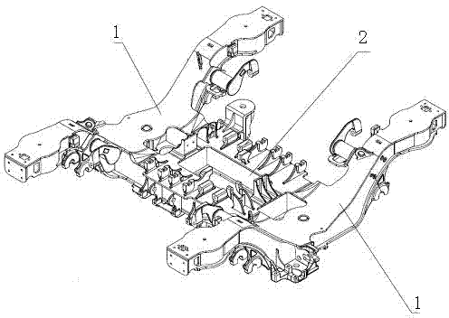
Standard motor train unit power bogie frame

A technology for power bogies and EMUs, applied in bogies, railway car body parts, transportation and packaging, etc., can solve the problems of weak anti-fatigue performance, unfavorable welding seam fatigue performance, and inability to transmit stress evenly, to meet international requirements. Advanced standards, to meet safe and reliable operation, to achieve the effect of smooth transfer

Inactive Publication Date: 2015-08-19
CRRC CHANGCHUN RAILWAY VEHICLES CO LTD
View PDF5 Cites 5 Cited by
  • Summary
  • Abstract
  • Description
  • Claims
  • Application Information

AI Technical Summary

Problems solved by technology

[0005] (3) The large-mass driving device on the frame is directly installed on the beam, and its frequent working conditions lead to very severe stress conditions in the connection area, which leads to the weak point of fatigue resistance in the connection area during the service period of the frame
[0007] (1) The multi-pass connection welds on each side are located in similar areas, resulting in a seriously low strength level in this area, so this connection area belongs to the weak area of ​​the frame; therefore, the quality level of the welds is required to be high, and at the same time It belongs to the high-risk area during the service period of the structure;
[0008] (2) The rigidity of the intermediate transitional structure is too large, which leads to the inability to uniformly transmit the stress of the beam and the side beam when the frame is loaded, and inevitably forms a stress concentration area near it, thus causing the nearby connecting welds to bear high stress in a large density. The fatigue performance of the weld is very unfavorable

Method used


Image

  • Standard motor train unit power bogie frame
  • Standard motor train unit power bogie frame
  • Standard motor train unit power bogie frame

Examples


Embodiment Construction

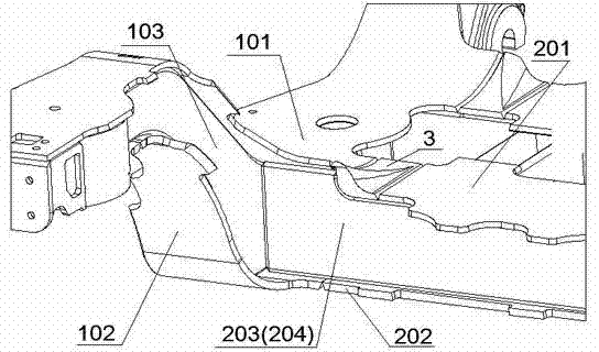
[0015] refer to figure 1 , figure 2 , the main body is composed of two side beams 1 and a beam 2, the main body of the side beams and the beams adopts a box-type welding structure, and is connected in a plug-in manner. The plate 101 is extended inwardly to realize variable cross-section docking through the connecting block 3 and the upper cover plate 201 of the beam. The connecting block 3 is a space curved surface structure. The plate 203 and the inner vertical plate 204 respectively extend outward and insert into the side beam 1 and directly connect with the inner vertical plate 103 of the side beam.

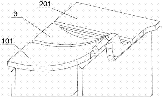
[0016] refer to image 3 , for the variable cross-section connection between the beam top cover plate 201 and the side beam top cover plate 101, the equal-strength connection is satisfied, that is, the cross-section change does not cause stress concentration and the stress level is equivalent. In order to achieve better connection functions on both sides, the upper and low...


PUM


Abstract

Disclosed is a standard motor train unit power bogie frame. The standard motor train unit power bogie frame is characterized in that side beams and a beam are connected in splicing and variable section mode, an upper cover plate of each side beam extends inwards, and achieves variable section butting against an upper cover plate of the beam through a connection block, the connection block is of a space curved face structure, a lower cover plate of each side beam extends inwards, and butts against a lower cover plate of the beam, and an outer stand plate and an inner stand plate of the beam respectively extend outward, and are inserted into the side beams and directly connected with inner stand plates of the side beams. Section variation of the standard motor train unit power bogie frame can not cause stress concentration and achieves comparable stress level. The connection block is of the space curved face structure, and achieves smooth transition from the upper cover plates of the side beams to the upper cover plate of the beam on geometrical characteristics, and therefore smooth transmission of stress between the upper cover plates of the side beams and the upper cover plate of the beam is achieved. Continuous transition of a box-like structure can be achieved, and rigidity value of the major structure of the standard motor train unit power bogie frame is at the mean value level, and then a rigidity increase on a connection area and stress concentration caused by the rigidity increase are avoided.

Description

technical field [0001] The invention relates to a frame, in particular to an improved low-stress power bogie frame of an EMU. Background technique [0002] One type of the existing high-speed EMU power bogie frame is that the crossbeam is a round steel pipe structure, which needs to be connected to the side beams on both sides through a transition structure, and other functional parts are welded to the round steel pipe crossbeam and the two side beams respectively. The beam structure of this frame is relatively simple, and its bearing capacity is relatively high. But there is the following problem at the junction of the beam and the two side beams: [0003] (1) There is a geometric mutation in the cross-section of the connection, the overall stress of the frame cannot be uniformly transmitted, and there will be stress concentration, which belongs to the weak area of ​​the frame's bearing capacity; [0004] (2) In order to meet the strength requirements of this connection a...

Claims


Application Information

Patent Timeline
IPC IPC(8): B61F5/52
CPCB61F5/52
Inventor 杨集友范军谷安斯韩庆利刘兆金王艳爽周殿买李国栋
Owner CRRC CHANGCHUN RAILWAY VEHICLES CO LTD
Learn More