Electric split axial-flow type regulating valve

An axial-flow, regulating valve technology, applied in the field of regulating valves, can solve the problems that the sealing surface of the piston cannot be tightly fitted, the sealing performance of closing and cutting can be reduced, and the error of installation size cannot be adjusted, so as to improve the sealing performance of closing and cutting, and the sealing performance of closing and cutting can be improved. The effect of high sealing performance and reducing the difficulty of production and assembly

Active Publication Date: 2015-08-19
四川长仪油气集输设备股份有限公司
View PDF9 Cites 5 Cited by
  • Summary
  • Abstract
  • Description
  • Claims
  • Application Information

AI Technical Summary

Problems solved by technology

However, in actual operation, it has the defect of "low cut-off sealing performance when closing". Yes, due to the inevitable machining dimensional errors of each part in production, there will always be a certain amount of installation dimensional errors superimposed after assembly. However, the connecting rod swing arm mechanism of the current axial flow valve pushes the piston to form a seal with the valve seat. The "limit position" of the pair is fixed and non-adjustable, that is to say, it cannot adjust the "limit position" of the piston to compensate for the "installation size error caused by assembly superposition".
When the "installation size error" is large, the phenomenon that the piston sealing surface cannot be tightly fitted to the valve seat will reduce the closing and cutting sealing performance. In severe cases, the sealing pair will fail and cause equipment accidents that cannot be closed and cut off.
This is one of the main reasons why the current axial flow valve has the technical defect of "low shut-off and sealing performance", and this is also a technical subject that the current axial flow valve products need to be further improved

Method used


Image

  • Electric split axial-flow type regulating valve
  • Electric split axial-flow type regulating valve
  • Electric split axial-flow type regulating valve

Examples


Embodiment Construction

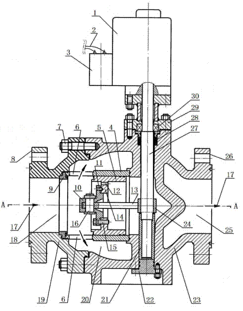
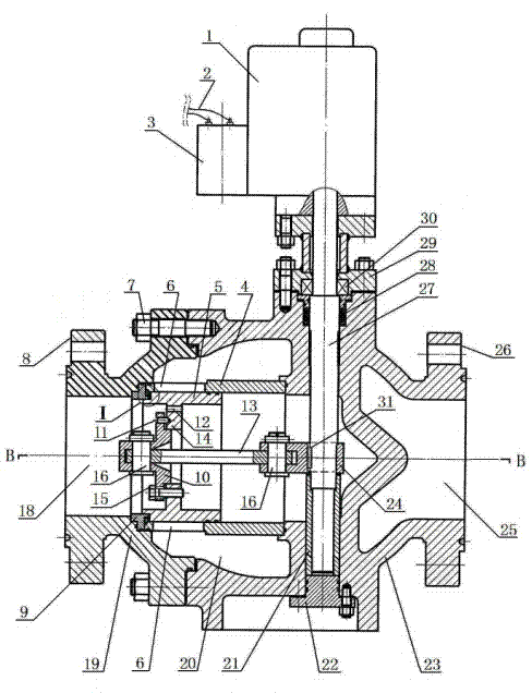
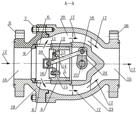
[0022] Embodiments of the present invention are further described below in conjunction with the accompanying drawings:

[0023] An electric split axial flow control valve proposed by the present invention is mainly composed of a main valve body 23, a left valve cover 19 connected and installed on the main valve body 23, an electric head 1, and a valve fitted in the main valve body 23. Seat 9, valve sleeve 4, spool 5, adjustment disc 10, pull rod 13, steering crank arm 24, adjustment valve rod 27 and guide sleeve 21, are embedded in the matching surface of the upper rod section of the main valve body 23 and the adjustment valve rod 27 The sealing stuffing box 28 is installed, and the sealing stuffing box 28 adopts the alternate sealing structure of "O-ring-PTFE packing", and the upper valve cover 29 of the sealing stuffing box 28 is installed on the main valve body 23 , the upper valve cover 29 is equipped with a thrust bearing 30, the upper rod end of the regulating valve rod ...


PUM


Abstract

The invention discloses an electric split axial-flow type regulating valve. The electric split axial-flow type regulating valve is characterized in that a crank connecting rod mechanism composed of a regulating valve rod, a turning crank arm, a pull rod, a regulating disc and a valve core and a regulating locking mechanism composed of a regulating bolt, a locking bolt and a regulating disc are assembled in the split valve body. The electric split axial-flow type regulating valve is convenient to pull and regulate the sealing position when the valve core is closed so as to compensate the mounting size error generated by producing, assembling and overlapping components, the valve core is firmly locked after regulating, the sealing surface of the valve core is capable of closely fitting with the valve seat sealing surface to form a tight and effective sealing pair, and the cut-off sealing performance of the axial-flow type regulating valve is greatly improved under the closed state. The trial proves that the electric split axial-flow type regulating valve has prominent advantages of simple structure, low manufacturing cost, convenience in production, assembly and regulation, fast regulation reaction speed, stable running, small vibration noise, large flow rate, small pressure drop and high cut-off sealing performance under closed state, and the electric split axial-flow type regulating valve is especially suitable for conveying pipelines of the petrochemical industry.

Description

technical field [0001] The invention relates to a control valve, which belongs to the technical field of transmission and distribution pipeline network control equipment, in particular to an electric split axial flow control valve, which is especially suitable for installation and use on transmission and distribution pipelines in the petrochemical industry. Background technique [0002] We know that the regulating valve is a special device installed on the pipeline to regulate the flow of the conveying medium. The most commonly used in the conveying pipeline network is a conventional regulating valve with an "S"-shaped flow channel in the inner cavity of the valve. Its basic structure is: the displacement direction of the spool is perpendicular to the pipeline axis. Although this conventional control valve has the advantages of simple structure, low production cost and convenient installation and use, it has uneven force on the valve cavity, large pressure loss of the convey...

Claims


Application Information

Patent Timeline
Patent Type & Authority Applications(China)
IPC IPC(8): F16K3/30F16K31/04F16K31/52
CPCF16K3/30F16K31/043F16K31/523
Inventor 王元清王元义魏连康黄世强宋书中王阳张月伟陈林云陈永忠赵文谭乐嘉李承阳徐忠成刘畅杨抚
Owner 四川长仪油气集输设备股份有限公司
Why Eureka
Try Eureka