Electro-hydraulic type high-frequency fatigue testing machine and design method thereof

A fatigue testing machine and high-frequency technology, applied in the field of fatigue testing machines, can solve the problems of unfavorable high-frequency generator high-frequency oscillation, difficult groove processing, uncontrollable sealing force, etc. The effect of dynamic sealing

Active Publication Date: 2015-08-19
SICHUAN DEXIANG KECHUANG INSTR
View PDF6 Cites 2 Cited by
  • Summary
  • Abstract
  • Description
  • Claims
  • Application Information

AI Technical Summary

Problems solved by technology

[0006] The purpose of the present invention is to overcome the oil hole design of the arc-shaped grooves on the moving disk and the static disk existing in the prior art. Due to the requirement of high-frequency vibration of the high-frequency generator, and the lack of uncontrollable sealing force of the joint surface of the moving plate and the static plate, an electro-hydraulic high-frequency fatigue testing machine is provided. The structural design of the high-frequency generator of the testing machine is more Reasonable, conducive to processing and realizing high-frequency requirements, and can also adjust the sealing pressure of the dynamic and static discs in the high-frequency generator to reduce the loss of drive power and energy consumption of the servo motor

Method used


Image

  • Electro-hydraulic type high-frequency fatigue testing machine and design method thereof
  • Electro-hydraulic type high-frequency fatigue testing machine and design method thereof
  • Electro-hydraulic type high-frequency fatigue testing machine and design method thereof

Examples


Embodiment 1

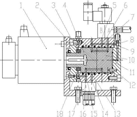
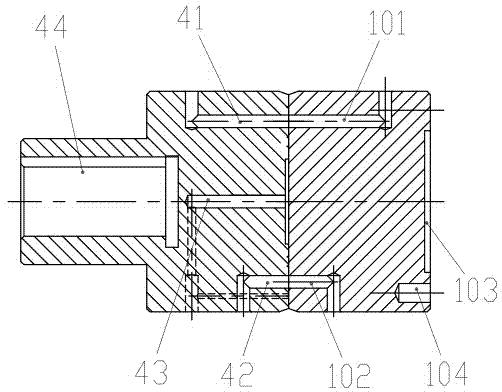
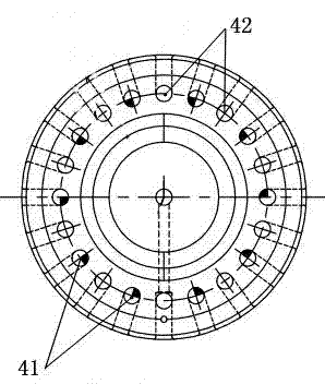
[0045] Such as Figure 1 to Figure 5 As shown, the high-frequency generator structure of the electro-hydraulic high-frequency fatigue testing machine includes a moving plate 4 and a static plate 10 whose end faces are in contact with each other, and a casing is arranged outside the moving plate and the static plate to seal them. A plurality of circular pressure oil holes 42 and oil return holes 41 of the moving disk are drilled and reamed on the contact end surface of the moving disk 4, and a static disk pressure oil hole 101 and a static Disk oil return hole 102, the static disk pressure oil hole 101 is arranged correspondingly to the moving disk pressure oil hole 42, and the static disk oil return hole 102 is arranged correspondingly to the moving disk oil return hole 41, so that when the moving disk 4 rotates, the moving disk The disk pressure oil hole 42 and the moving disk oil return hole 41 can communicate with the static disk pressure oil hole 101 and the static disk oi...

Embodiment 2

[0089] In this embodiment, the number of pressure oil holes and oil return holes on the end face of the moving disk is set to 5, then the static disk corresponding to the moving disk is provided with 5 pressure oil holes and 5 oil return holes, and the pressure oil The holes and oil return holes are evenly spaced on the same circular line of the end face, the number of oil holes on the end face of the moving disc is 10, and the number of oil holes on the end face of the static disc is also 10. Other settings are the same as those in Embodiment 1. In this embodiment, each rotation of the moving plate can generate 10 oscillations, which is beneficial to reduce the speed of the drive motor compared with the prior art where only 2 oscillations per rotation , and at the same time meet the requirements of the limit speed of the bearing, which is more conducive to improving the high-frequency frequency of the fatigue testing machine.

[0090] All features disclosed in this specificat...


PUM

PropertyMeasurementUnit
diameteraaaaaaaaaa
diameteraaaaaaaaaa
diameteraaaaaaaaaa

Abstract

The invention discloses a fatigue testing machine and a design method thereof. An electro-hydraulic type high-frequency fatigue testing machine comprises a movable disk and a static disk which are in contact with each other from the end surfaces, wherein shells are arranged outside the movable disk and the static disk for sealing the movable disk and the static disk; the contact end surface of the movable disk is hinged to a plurality of circular movable disk pressure oil holes and movable disk oil return holes; static disk pressure oil holes and static disk oil return holes are formed in the static disk end surface in contact with the movable disk; the oil holes in the static disk correspond to the oil holes in the movable disk; when the movable disk rotates, the movable disk pressure oil holes and the movable disk oil return holes can be respectively communicated with the static disk pressure oil holes and the static disk oil return holes; a channel for pumping pressure oil into the end face and a device for controlling the pressure oil amount of the channel are arranged on the end part, which is far away from the movable disk, of the static disk. The high-frequency generator of the testing machine is reasonable in structural design and favorable for processing and high-frequency demand implementation; furthermore, the sealing pressure on the movable disk and the static disk in the high-frequency generator can be adjusted, so that the driving power of a servo motor and the energy loss can be reduced.

Description

technical field [0001] The invention relates to a fatigue testing machine, in particular to an electro-hydraulic high-frequency fatigue testing machine and a design method thereof. Background technique [0002] Ordinary hydraulic fatigue testing machines usually control the reciprocating motion of the actuator with a certain pressure and a certain flow of hydraulic oil through the servo valve, and alternately pull and compress the load on the specimen to realize the fatigue test. The actuator is a high-precision double-rod double-extension fully symmetrical oil cylinder. A load sensor is installed at the front end of the actuator to detect the load force value, and a hysteresis displacement sensor (or external LVDT displacement sensor) is installed at the end of the actuator. sensor) to detect the displacement (or amplitude) of the movement; through the measurement and control system, the load force or displacement (amplitude) value can be selected to control reciprocating l...

Claims


Application Information

Patent Timeline
Patent Type & Authority Applications(China)
IPC IPC(8): G01N3/36G01N3/02
Inventor 阙永德
Owner SICHUAN DEXIANG KECHUANG INSTR
Why Eureka
Try Eureka