
Rotary disc-type microfluidic concentration measuring apparatus and method based on luminosity detection

A concentration measurement and detection device technology, applied in the direction of color/spectral characteristic measurement, etc., can solve the problems that the concentration value of the object to be detected cannot be known in advance, cannot be applied, and the optimal optical path value is difficult to judge in advance, so as to make up for the detection accuracy defect , reduce detection error, easy to carry effect

Active Publication Date: 2015-08-19
天裕(无锡)装备技术有限公司
View PDF9 Cites 19 Cited by
  • Summary
  • Abstract
  • Description
  • Claims
  • Application Information

AI Technical Summary

Problems solved by technology

However, in the actual detection process, the concentration value of the substance to be detected is often not known in advance, so it is difficult to judge in advance the selection of the optimal optical path value
In addition, this device is only suitable for photometric detection on a traditional scale, and is often not applicable to microfluidic photometric detection systems that require a higher optical path

Method used


Image

  • Rotary disc-type microfluidic concentration measuring apparatus and method based on luminosity detection
  • Rotary disc-type microfluidic concentration measuring apparatus and method based on luminosity detection
  • Rotary disc-type microfluidic concentration measuring apparatus and method based on luminosity detection

Examples


Embodiment Construction

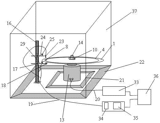
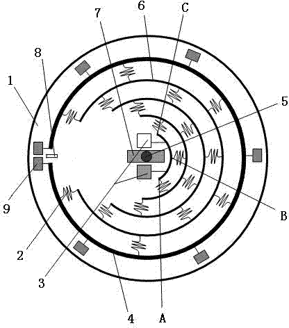
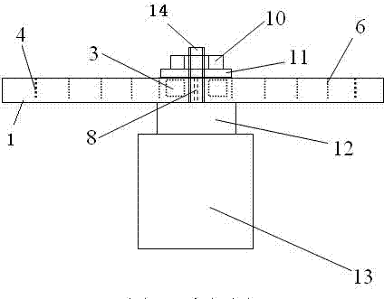
[0024] see figure 1 , is the overall structure diagram of a rotating disk microfluidic concentration measuring device based on photometric detection in the present invention. Inside a sealed darkroom 37, components such as a rotating disk microfluidic chip 1, an experimental device base 22, a photometric detection device bracket 16, and an AC servo motor 13 are arranged. Wherein, the experimental device base 22 is fixed on the bottom wall of the sealed darkroom 37, the photometric detection device support 16 is perpendicular to the experimental device base 22, and is also perpendicular to the bottom surface of the sealed darkroom 37, and the bottom of the photometric detection device support 16 is vertically welded and fixed In the center of the experimental device base 22 and the sealed dark room 37 near the left edge. The base 22 of the experimental device and the bracket 16 of the photometric detection device constitute the most basic supporting frame of the whole device....


PUM


Abstract

The invention discloses a rotary disc-type microfluidic concentration measuring apparatus and method based on luminosity detection. A rotary disc-type microfluidic chip, a luminosity detection device support and an AC servo motor are arranged in a hermetic darkroom; an output shaft motor shaft of the AC servo motor is vertically upward and is coaxially equipped with the horizontal rotary disc-type microfluidic chip; and N stages of test solution interinfiltration bands are arranged on the rotary disc-type microfluidic chip, each stage of test solution interinfiltration band is in the shape of a circular arc with the center of the rotary disc-type microfluidic chip as the center of circle, and two adjacent stages of test solution interinfiltration bands are connected through a spring-like test solution channel and communicated with each other. According to the invention, effective positioning of dilution concentration is realized through combined usage of the rotary disc-type microfluidic chip and rotary dilution positioning technology, so a dilution ratio is rapidly calculated; the accurate concentration of a to-be-measured solution is backwardly deduced by multiplying the dilution ratio by corresponding relationship between known optical length and absorbance produced at optimal concentration; and sample introduction, detection and concentration calculation are automatically carried out.

Description

technical field [0001] The invention relates to microfluidic photometric detection technology, in particular to a microfluidic mixed solution concentration measurement device and method based on photometric detection. Background technique [0002] Microfluidic photometric detection technology is currently the most widely applicable microfluidic detection method. However, the photometric detection cell of the microfluidic chip is often fixed, and its optical path cannot be changed arbitrarily according to the concentration of the liquid to be detected. But according to the spectrophotometric error theory, the best absorbance in the measurement A OPT is 1 / ln10, and the corresponding optimal optical path length is 0.434 αC 0 ( C 0 is the concentration of absorbate in the solution, α is the absorbance coefficient of the absorber). Therefore, only when the concentration is compatible with the detection optical path, the photometric detection noise is the smallest, and the ...

Claims


Application Information

Patent Timeline
Patent Type & Authority Applications(China)
IPC IPC(8): G01N21/31
Inventor 杨宁黄余项昌华张荣标孙俊
Owner 天裕(无锡)装备技术有限公司
Learn More