Micro-lens array light guide plate with adaptive spacing

A technology of microlens array and light guide plate, applied in lens, light guide, optics and other directions, can solve the problems of low production precision of light guide plate, low light uniformity, complicated production process, etc. The effect of high light efficiency

Inactive Publication Date: 2015-08-19
SOUTH CHINA UNIV OF TECH
View PDF8 Cites 8 Cited by
  • Summary
  • Abstract
  • Description
  • Claims
  • Application Information

AI Technical Summary

Problems solved by technology

[0003] The purpose of the present invention is to overcome the problems of low manufacturing precision, low light guide efficiency, low light uniformity, low production efficiency and complicated manufacturing process of the light guide plate in the prior art, and provide a microlens array light guide plate with self-adaptive spacing

Method used


Image

  • Micro-lens array light guide plate with adaptive spacing
  • Micro-lens array light guide plate with adaptive spacing
  • Micro-lens array light guide plate with adaptive spacing

Examples


Embodiment 1

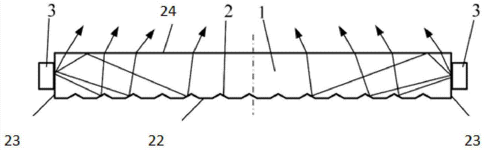
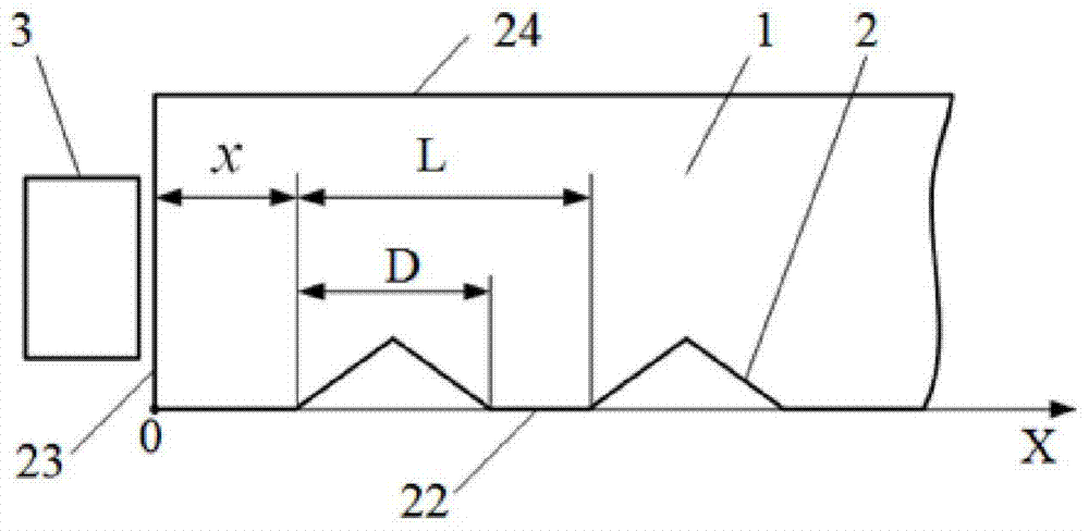
[0029] In one embodiment of the present invention, as figure 1 and figure 2 As shown, a microlens array light guide plate with adaptive spacing includes a light guide plate 1, and the reflective surface 22 of the light guide plate 1 is provided with a number of reflections parallel to each other and parallel to one side of the light guide plate 1 or V-shaped protrusions. The surface lens structure 2, the reflective surface lens structure 2 of this embodiment is V-groove shape, the said reflective surface lens structure 2 is left and right symmetrically distributed with respect to the center line of the light guide plate 1, and the adjacent two reflective surface lens structures 2 The distance d3 is set incrementally from both sides of the light guide plate 11 to the middle of the light guide plate 1, and its value is 30-5000 microns. The material of the light guide plate 1 in this embodiment is an acrylic plate.

[0030] The included angle between the two sides of the reflec...

Embodiment 2

[0034] The difference between this embodiment and Embodiment 1 is that: the light exit surface 24 of the light guide plate 1 is also provided with a number of V-groove or V-protrusion-shaped light exit surface lens structures 5 parallel to each other and one side of the light guide plate 1 at the same time, In this embodiment, V-groove-shaped lens structures 5 on the light-emitting surface are used. The lens structures 5 on the light-emitting surface are distributed at equal intervals, and the distance d1 between adjacent lens structures 5 on the light-emitting surface is 30-2000 microns.

[0035] The included angle between the two sides of the light-emitting surface lens structure 5 is 30-170 degrees, and the depth or height is 0.01-0.2 mm.

[0036] In this embodiment, a V-groove-shaped light-emitting surface lens structure 5 is provided on the light-emitting surface 24 to further play the role of scattering light and improve the light-guiding efficiency, light-emitting unifor...

Embodiment 3

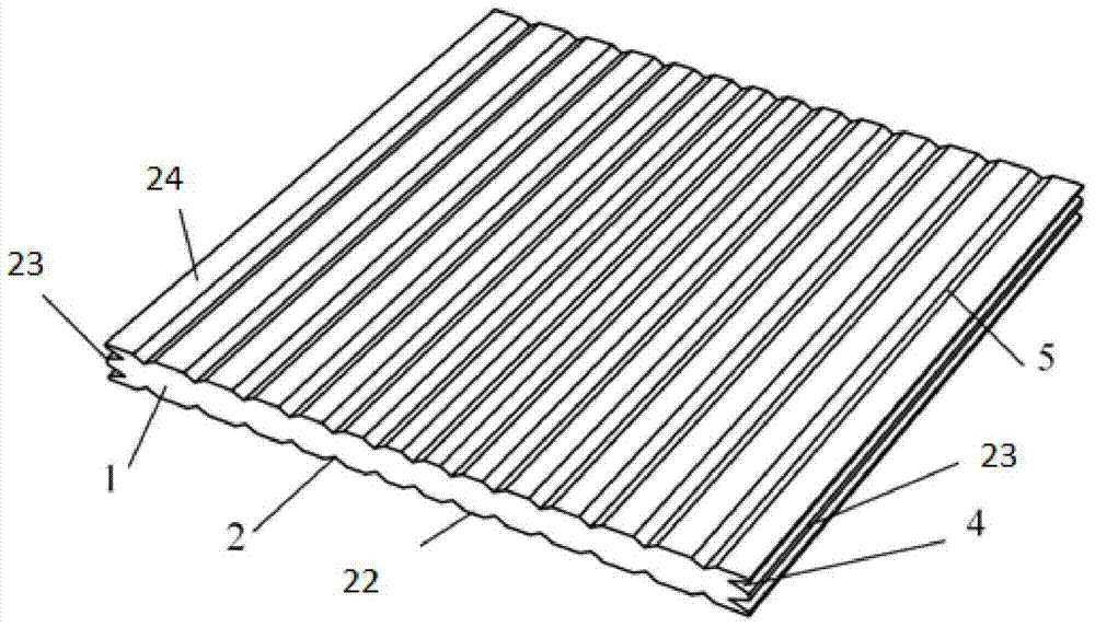
[0038] like image 3As shown, the difference between this embodiment and the second embodiment is that: the light incident side 23 of the light guide plate 1 is also provided with a number of V-groove-shaped or V-shaped light incident surfaces parallel to one side of the light guide plate 1 at the same time. Surface lens structures 4, the light incident surface lens structures 4 are equally spaced, and the distance d2 between adjacent light incident surface lens structures 4 is 30-2000 microns.

[0039] The included angle between the two sides of the light incident surface lens structure 4 is 30-170 degrees, and the depth or height is 0.01-0.2 mm.

[0040] like image 3 As shown, the V-groove-shaped reflective surface lens structure 2 on the reflective surface 22 of the light guide plate 1 and the V-groove-shaped light-exit surface lens structure 5 on the light-exit surface 24 are distributed in an array, and both are parallel to an edge line on the surface of the light guide...


PUM


Abstract

The invention discloses a micro-lens array light guide plate with adaptive spacing. The micro-lens array light guide plate comprises a light guide plate, a reflection surface of the light guide plate is provided with a plurality of V-groove-shaped or V-shaped protruding reflection plane lens structures parallel to each other and parallel to one edge of the light guide plate, the reflection surface lens structures are arranged in symmetry relative to the center line of the light guide plate, the spacing between the two adjacent reflection plane lens structures is ascended from two sides of the light guide plate to the center of the light guide plate, the value of the spacing ranges from 30 to 5000 micrometers, the included angle between two side surfaces of the reflection surface lens structures is 30-170 degrees, and the depth or the height is from 0.01 to 0.5 mm. According to the micro-lens array light guide plate, the luminous efficiency and the brightness are high, the light emission is more uniform, the light guide plate is light, the cost is low, the efficiency is high, and environmental protection is realized.

Description

technical field [0001] The invention relates to the fields of LED lighting design and precision photoelectric component manufacturing, in particular to a microlens array light guide plate with self-adaptive spacing. Background technique [0002] At present, LED panel lights mainly adopt two types: direct type and side entry type. The present invention mainly relates to a light guide plate of side entry type panel light. Upper side-entry panel lights dominate. At present, there are printing type, chemical etching type, laser engraving type and micro-cutting engraving type etc. for the light guide plate of flat panel light. The cost of printing is relatively low and it is suitable for the production of large-sized light guide plates, but the viscosity of the ink is not easy to control, the accuracy is not high, and the shortcomings of pollution have been gradually eliminated; the disadvantage of chemical etching is that the optical surface is relatively rough. The depth of d...

Claims


Application Information

Patent Timeline
Patent Type & Authority Applications(China)
IPC IPC(8): G02B6/00G02B3/00
Inventor 谢晋司贤海邓振杰冯彦科
Owner SOUTH CHINA UNIV OF TECH
Why Eureka
Try Eureka