Laser transmission beam jitter effect numerical simulation method

A beam jittering and numerical simulation technology, applied in optics, optical components, instruments, etc., can solve the problems such as the inability to apply numerical simulation of the beam jittering effect of laser transmission, and achieve the effect of high accuracy and simple operation.

Inactive Publication Date: 2015-08-19
NO 63655 TROOPS OF THE CHINESE PEOPLES LIBERATION ARMY
View PDF3 Cites 2 Cited by
  • Summary
  • Abstract
  • Description
  • Claims
  • Application Information

AI Technical Summary

Problems solved by technology

[0006] However, the existing technology can only estimate the laser-to-target power density, but it cannot be applied to the numerical simulation of the beam jitter effect of laser transmission

Method used


Image

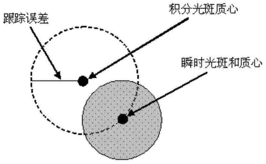
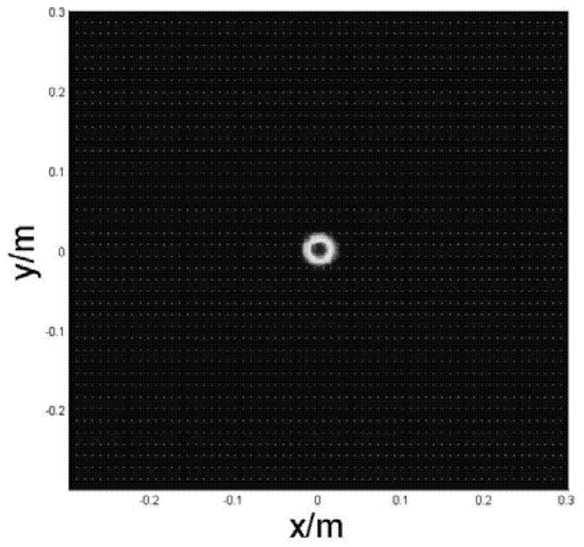
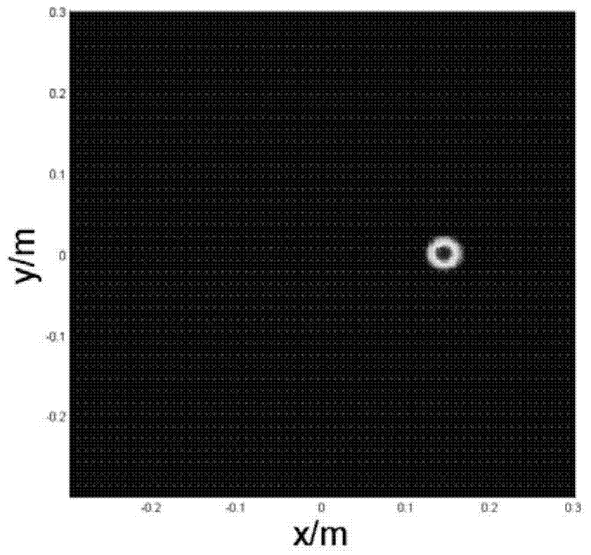
  • Laser transmission beam jitter effect numerical simulation method
  • Laser transmission beam jitter effect numerical simulation method
  • Laser transmission beam jitter effect numerical simulation method

Examples


Embodiment Construction

[0033] The present invention is described in further detail below in conjunction with accompanying drawing:

[0034] The numerical simulation method of the shaking effect of the laser transmission beam of the present invention comprises the following steps:

[0035] 1) Generate a set of uniformly distributed random numbers of 0-2π as the direction angle θ perpendicular to the transmission plane 1 , to generate a set of Gaussian distribution random numbers whose root mean square is σ as the upward direction angle θ 2 ;

[0036] 2) According to θ 1 and θ 2 with Zernike polynomial first order coefficient a 1 and the second order coefficient a 2 The relationship between get Zernike polynomial first order coefficient a 1 and the second order coefficient a 2 ;

[0037] 3) According to the first-order coefficient a of the Zernike polynomial 1 and the second order coefficient a 2 Compute the tilted wavefront phase;

[0038] 4) The tilted wavefront phase is superimposed on t...


PUM


Abstract

The invention discloses a laser transmission beam jitter effect numerical simulation method comprising the following steps that 1) supposing to be isotropic in beam jittering, jitter angle root mean square is sigma, and two sets of random numbers theta 1 and theta 2 are generated under polar coordinates, wherein theta 1 is a uniform random number from 0 to 2pi, and theta 2 is a gaussian random number of which root mean square is sigma; 2) a Zernike polynomial first-order coefficient a1 and a second-order coefficient a2 are obtained according to the relation between theta 1 and theta 2 and Zernike polynomial first-order coefficient a1 and second-order coefficient a2; 3) tilted wavefront phase is calculated according to Zernike polynomial first-order coefficient a1 and second-order coefficient a 2; and 4) the tilted wavefront phase superposed on a light field emitting beams so that laser transmission beam jitter effect numerical simulation is realized. Laser transmission beam jitter effect numerical simulation can be realized by the Laser transmission beam jitter effect numerical simulation method.

Description

technical field [0001] The invention relates to a numerical simulation method, in particular to a numerical simulation method for the shaking effect of a laser transmission beam. Background technique [0002] During the actual atmospheric transmission of the laser, the factors affecting the power density on the target plane mainly include the characteristics of the laser itself, the linear and nonlinear effects generated during the atmospheric transmission, and so on. The characteristics of the laser itself mainly include the distribution of the beam exit, the tracking accuracy of the laser emission system, etc. The linear and nonlinear effects produced during the atmospheric transmission mainly include the atmospheric refraction effect caused by the uneven atmospheric density on the laser transmission path, the absorption and Scattering effects, turbulence effects such as beam expansion, beam drift, and light intensity scintillation caused by uneven atmospheric density, and...

Claims


Application Information

Patent Timeline
IPC IPC(8): G02B27/00G02B27/48
CPCG02B27/0012G02B27/48
Inventor 常金勇强希文胡月宏宗飞赵军卫冯建伟吴敏封双连李志朝
Owner NO 63655 TROOPS OF THE CHINESE PEOPLES LIBERATION ARMY
Why Eureka
Try Eureka