Double-scale accurate constant-speed and quantitative regulator for transfusion

A regulator and double-scale technology, applied in the field of medical devices, can solve the problems of high price of infusion pumps, time-consuming installation and debugging, not intuitive and simple, etc. Effect

Inactive Publication Date: 2015-08-26
泗水惠好医院
View PDF6 Cites 1 Cited by
  • Summary
  • Abstract
  • Description
  • Claims
  • Application Information

AI Technical Summary

Problems solved by technology

It cannot be applied when precise control of flow rate regulation is required
[0005] Infusion pumps are commonly used when precise control of the infusion flow rate is required, but the infusion pumps are expensive, unfavorable for popularization, and the operation is too complicated, not intuitive and simple enough, especially when the condition of ordinary patients changes suddenly, it takes time to install and debug before they can be put into use

Method used


Image

  • Double-scale accurate constant-speed and quantitative regulator for transfusion
  • Double-scale accurate constant-speed and quantitative regulator for transfusion
  • Double-scale accurate constant-speed and quantitative regulator for transfusion

Examples


Embodiment 1

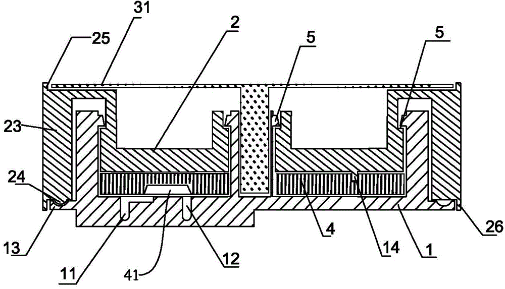
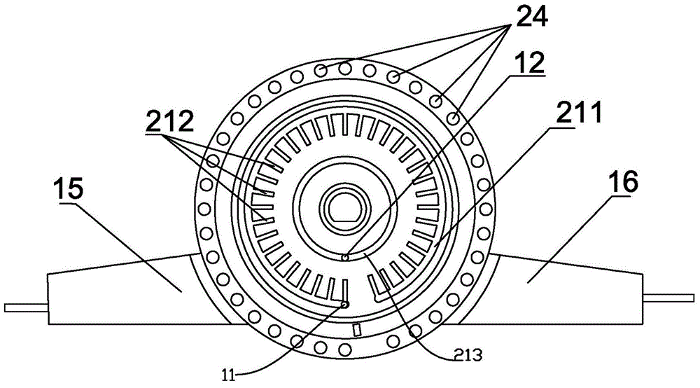
[0076] Double-scale precise fixed-speed and quantitative regulator for infusion, including a fixed base 1, a liquid inlet 11 and a liquid outlet 12 are arranged under the fixed base 1, a fixed shaft extends upward from the middle of the fixed base 1, and side walls extend upward from the edge. There are upper and lower buckles 5 on the shaft and the side wall, and the movable flow rate regulating plate 2 is fixed through the buckles 5; the cut-off position and the gasket 4 are located between the fixed base 1 and the flow rate regulating plate 2; the fixed base 1 The main liquid inlet tank 211 and the main liquid outlet tank 213 respectively connected with the liquid inlet 11 and the liquid outlet 12 are arranged on the top, and the speed regulating grooves 212 with different apertures are distributed radially on one side of the main liquid inlet tank 211 , the speed regulating groove 212 communicates with one end of the groove 41 on the gasket 4, and the other end of the groov...

Embodiment 2

[0083] refer to Figure 5-8 , the structure of the regulator is basically the same as in Example 1, the difference is that the realization of the flow rate adjustment is different, and the setting of the support plate is also changed accordingly:

[0084] The flow rate adjustment plate 2 is provided with a liquid inlet 11, the fixed base 1 is provided with a liquid outlet 12, and the flow rate adjustment plate 2 is provided with a flow rate adjustment channel. The flow rate adjustment channel is composed of a main groove 211 and speed-regulating recesses of different apertures communicated with the main groove. The main groove 211 is connected with the liquid inlet 11, the other end of the speed regulating groove 212 is connected with the through hole on the gasket 4, and the other end of the through hole on the gasket 4 is connected with the liquid outlet 12 of the fixed base 1. In communication, the gasket 4 is fixed on the fixed base 1 through the positioning column 14 prov...


PUM


Abstract

The invention discloses a double-scale accurate constant-speed and quantitative regulator for transfusion. The regulator comprises a fixed base; a liquid inlet and a liquid outlet are formed below the fixed base; a movable flow speed adjusting plate is fixed above the fixed base; a seal gasket is arranged between the fixed base and the flow speed adjusting plate; a passage communicated with the liquid inlet and the liquid outlet is formed in the seal gasket; the transfusion flow speed regulation is achieved by using passages of different pore diameters; a flow speed identification is arranged on the regulator, and comprises a dial and a corresponding flow speed indicator. According to the regulator, through the change of the liquid passage, the transfusion flow speed and flow are accurately, quickly and stably controlled, meanwhile, the transfusion flow speed and the transfusion flow are conveniently and intuitively read, the single hand operation is facilitated, the regulator meets various clinical use habits and various application environments, and the transfusion safety is ensured. When the state of an illness of a common patient deteriorates suddenly, the urgent requirement of accurate control of transfusion is quickly met, and the aid time is gained.

Description

technical field [0001] The invention relates to a medical device, in particular to a flow rate regulator for transfusion. Background technique [0002] Flow rate control during infusion is very important. A reasonable flow rate can help improve efficacy and reduce risks during infusion. In clinical practice, doctor’s orders are usually issued at the rate of drops, and when the condition is serious or there are special needs, they will be issued at the flow rate. Special medication requires the flow rate to be as accurate as “drips”. In particular, when infusion is performed on cardiac insufficiency, children, newborns, elderly patients, and critically ill patients, if the infusion speed is too fast, too much fluid enters the body per unit time or the drug dose is too large, it will induce heart failure and excessive drop in blood pressure. Waiting fast makes the patient's condition worse. If the infusion speed is too slow, the fluid entering the body per unit time is insuf...

Claims


Application Information

Patent Timeline
Patent Type & Authority Applications(China)
IPC IPC(8): A61M5/175
CPCA61M5/141A61M5/16813A61M2205/586A61M5/16804A61M5/16877A61M2205/3334A61M2205/3337
Inventor 胡绍勤汤丽芬
Owner 泗水惠好医院
Why Eureka
Try Eureka