
Gas condensation technology and equipment

A technology of gas condensation and equipment, applied in the direction of separation methods, dispersed particle separation, chemical instruments and methods, etc., can solve the problems of limited gas volume to be condensed, easy frosting on the wall of heat exchange tubes, and loss of condensation function, etc., to achieve improved Operational efficiency, low cost, heat energy and time saving effects

Active Publication Date: 2015-08-26
爵翔(上海)能源科技有限公司
View PDF6 Cites 11 Cited by
  • Summary
  • Abstract
  • Description
  • Claims
  • Application Information

AI Technical Summary

Problems solved by technology

[0004] 1. Adsorption: Use activated carbon, kaolin, etc. to adsorb volatile organic compounds, and then desorb volatile organic compounds from activated carbon or kaolin. However, due to the flammability of organic compounds, this method has certain safety hazards
[0005] 2. Absorption: Use water, acid or alkali to absorb volatile organic compounds. After absorption, some volatile organic compounds are transferred to water, acid or alkali, and some of them cannot be absorbed, and the absorbed water, acid or alkali need to be treated again. It can only be discharged later, the process is cumbersome and the cost is relatively high
If the temperature difference between the gas to be condensed and the cold source is large, whether it is a shell-and-tube condenser or a wound condenser, the heat exchange tube wall is prone to frost, and the heat exchange tube will be blocked after a long time, losing the condensation function
If defrosting the frosted condenser, heating is required, which not only requires additional energy, but also requires the condenser to stop working before defrosting, which limits the amount of condensed gas that can be processed

Method used


Image

  • Gas condensation technology and equipment
  • Gas condensation technology and equipment
  • Gas condensation technology and equipment

Examples


Embodiment Construction

[0065] In order to make the object, technical solution and advantages of the present invention clearer, various embodiments of the present invention will be described in detail below in conjunction with the accompanying drawings. However, those of ordinary skill in the art can understand that, in each implementation manner of the present invention, many technical details are provided for readers to better understand the present application. However, even without these technical details and various changes and modifications based on the following implementation modes, the technical solution claimed in each claim of the present application can be realized.

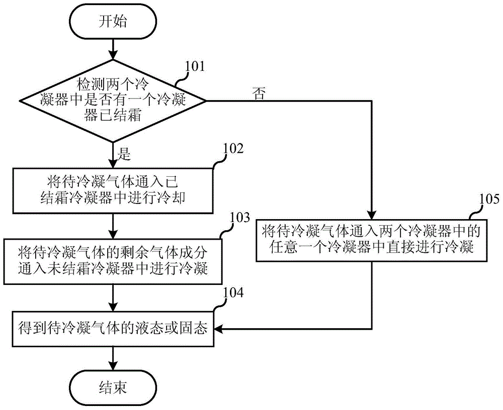
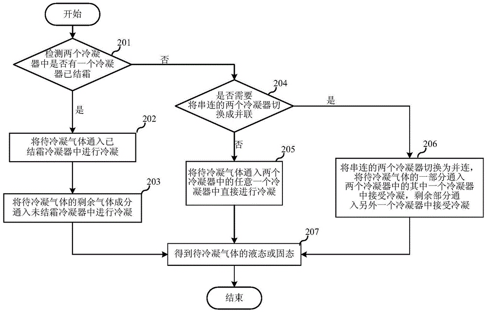
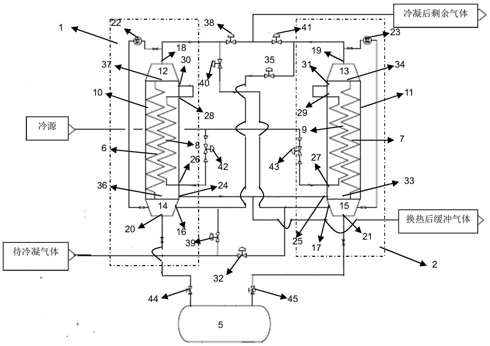
[0066] The first embodiment of the present invention relates to a gas condensation process, comprising the following steps:

[0067] Pass the gas to be condensed into two condensers in series for condensation to obtain the liquid or solid state of the gas to be condensed;

[0068] Among them, the gas to be condensed is firs...


PUM


Abstract

The invention belongs to the field of environmental protection technology, and discloses gas condensation technology and equipment. According to the gas condensation technology, gas to be condensated is delivered into two condensers successively for condensation so as to obtain a liquid product or a solid product of the gas to be condensated, wherein the two condensers are connected in series, the gas to be condensated is firstly delivered into one condenser which contains frost for cooling, and then is delivered into the other condenser which contains no frost for cooling. Compared with the prior art, the gas condensation technology is capable of realizing defrosting of the condenser which contains frost with the temperature of the gas to be condensated; forced inoperation caused by frosting of the condenser is avoided; condensation recovery of 99% of the gas to be condensated can be realized; energy loss is reduced, and energy is saved via reasonable thermal exchanging and full utilization of inner system energy.

Description

technical field [0001] The invention relates to environmental protection technology, in particular to a gas condensation process and equipment. Background technique [0002] In recent years, with the development of industry, in petrochemical, pharmaceutical, warehousing and other fields, various volatile organic compounds volatilize a relatively high concentration of organic vapors in the process of production, storage, transportation, sales and use, such as gasoline, aviation Kerosene, etc., not only waste resources, but also pollute the environment, and leave a major fire or explosion hazard, especially PM2. Particulate matter, the full spelling is Particulate Matter2.5) seriously affects ambient air quality, and fine particles below 2.5 microns mainly come from volatile organic compounds produced by fossil fuel combustion, especially small molecule volatile organic compounds such as alkanes, alkenes, and alkynes etc. These volatile organic compounds not only contain elem...

Claims


Application Information

Patent Timeline
Patent Type & Authority Applications(China)
IPC IPC(8): B01D53/00
Inventor 刘枫
Owner 爵翔(上海)能源科技有限公司
Learn More