
Decelerating clutch of washing machine and washing machine

A deceleration clutch and washing machine technology, applied in the field of washing machines, can solve problems such as poor overrunning clutch, large vibration of washing machines, failure of one-way bearings, etc., and achieve the effects of novel structure, improved cleaning ratio, and improved carrying capacity

Active Publication Date: 2015-08-26
QINGDAO HAIER WASHING MASCH CO LTD
View PDF7 Cites 1 Cited by
  • Summary
  • Abstract
  • Description
  • Claims
  • Application Information

AI Technical Summary

Problems solved by technology

[0006] However, in the washing machine with the above-mentioned deceleration clutch, the inner tub and the pulsator frequently run in opposite directions, and the moment of inertia generated by the inner tub directly acts on the overrunning clutch. quality problem
During the rotation of the inner tub, the one-way bearing will often have a reverse force, and the one-way bearing is prone to failure. At the same time, the clutch spring will be tightened during washing, resulting in damage to the clutch spring; The driving wheel is separated and connected to the reducer. The inner drum swings in the dehydration state, which directly acts on the dehydration shaft. The dehydration shaft is eccentric, causing the washing machine to vibrate and produce noise.

Method used


Image

  • Decelerating clutch of washing machine and washing machine
  • Decelerating clutch of washing machine and washing machine
  • Decelerating clutch of washing machine and washing machine

Examples


Embodiment 1

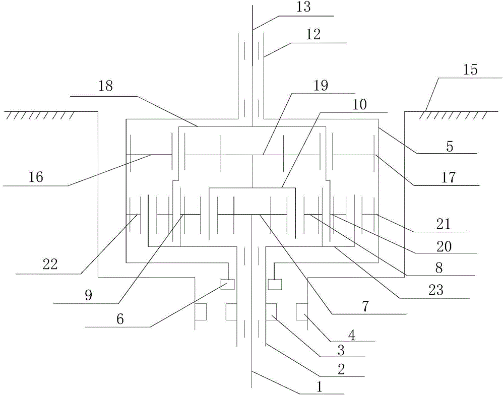
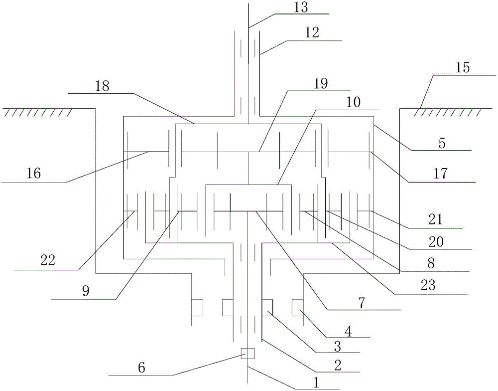
[0038] Such as figure 1 and figure 2 As shown, in the deceleration clutch of the washing machine described in this embodiment, the first gear train is a planetary gear train, mainly composed of the first sun gear 7, the first planetary gear 8, the first internal gear 9, the first planetary gear frame 10, the first sun gear 7 is installed on the input shaft 1, the first internal gear 9 is arranged in the cavity of the brake wheel 5, the first planetary gears 8 are evenly distributed on the same circumference of the first planetary wheel frame 10, and the first The planetary gear 8 meshes with the first sun gear 7 and the first internal gear 9 at the same time, the first internal gear 9 is connected with the input shaft sleeve 2 as a whole, and the first planetary gear carrier 10 is in transmission connection with the second gear train.

[0039] The second gear train is mainly composed of the second central gear 19, the second internal gear 17, the second planetary gear 16, an...

Embodiment 2

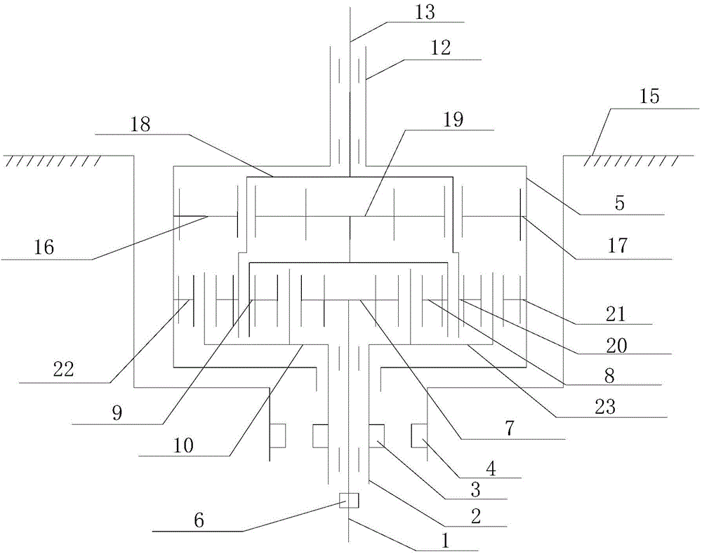
[0043] Such as image 3 As shown, the difference between this embodiment and the first embodiment lies in that the transmission connection relationship between the first gear train and the second gear train and the connection relationship between the first gear train and the input shaft sleeve 2 are different.

[0044] The first gear train is mainly composed of the first sun gear 7, the first planetary gear 8, the first internal gear 9, and the first planetary carrier 10. The first sun gear 7 is installed on the input shaft 1, and the first internal gear 9 is set In the chamber of the brake wheel 5, the first planetary gears 8 are evenly distributed on the same circumference of the first planetary gear carrier 10, and mesh with the first sun gear 7 and the first internal gear 9 at the same time, the first planetary gear carrier 10 and the input shaft The sleeve 2 is connected as a whole, and the first internal gear 9 is connected with the second wheel train in transmission.

...

Embodiment 3

[0047] Such as figure 1 As shown, the clutch device described in this embodiment includes a dehydration pin 6 installed on the lower end of the brake wheel 5, a clutch sleeve 3 installed on the input shaft sleeve 2 and rotating integrally with the input shaft sleeve, and a braking pin installed on the lower end of the housing 15. Pin 4 and driving clutch sleeve 3 are respectively connected to / disconnected with dehydration pin 6 and brake pin 4;

[0048] In the washing state, the drive unit controls the clutch sleeve 3 to be connected to the brake pin 4 and disconnected from the dehydration pin 6 . In the dehydration state, the drive unit controls the clutch sleeve 3 to be connected to the dehydration pin 6 and to be disconnected from the brake pin 4 .


PUM


Abstract

The invention discloses a decelerating clutch of a washing machine and the washing machine. The decelerating clutch comprises an input shaft, an input shaft sleeve, a brake wheel, a speed reducer, a water removal shaft, an output shaft, a clutch device and a casing, wherein the input shaft is sleeved with the input shaft sleeve, the water removal shaft is nested on the output shaft, the speed reducer is mounted in an inner cavity of the brake wheel, the input shaft, the input shaft sleeve, the brake wheel and the output shaft are connected with the speed reducer respectively, and the water removal shaft is integrally connected with the brake wheel; the speed reducer comprises three sets of wheel trains, namely, a first wheel train, a second wheel train and a third wheel train; the first wheel train and the second wheel train are drive chains between the input shaft and the output shaft, the second wheel train and the third wheel train are drive chains which are located between the output shaft and the brake wheel and between the output shaft and the water removal shaft and rotate reversely, and the input shaft sleeve is connected with the first wheel train and the third wheel train. The decelerating clutch has the characteristics of simple and compact structure, low manufacturing cost, safe, reliable and efficient drive, long service life and low noise.

Description

technical field [0001] The invention relates to the field of washing machines, in particular to a washing machine deceleration clutch and a washing machine. Background technique [0002] At present, the function of the deceleration clutch of the pulsator type washing machine is generally to drive the pulsator to reciprocate after decelerating the bidirectional rotation of the motor. The conventional deceleration clutch is mainly composed of an input shaft, an output shaft, an output shaft sleeve, an input shaft sleeve, a brake wheel, a reduction mechanism installed inside the brake wheel, and a clutch component installed on the input shaft sleeve. In washing conditions, the output shaft is required to rotate repeatedly at low speed in both directions. The output shaft sleeve and the brake wheel are integrated. The deceleration mechanism generally only plays a simple deceleration role. When the brake wheel is braked, the output shaft sleeve is also restrained. The two-way ro...

Claims


Application Information

Patent Timeline
Patent Type & Authority Applications(China)
IPC IPC(8): D06F37/40
CPCD06F37/40
Inventor 吕佩师杨林张刚金今井俊次
Owner QINGDAO HAIER WASHING MASCH CO LTD
Learn More