Valve of liquid operation

A fluid and fluid leakage technology, applied to fuel injection devices, engine components, machines/engines, etc. with stress-reducing measures, can solve problems such as damage and destruction of spring components, and achieve the effect of avoiding pressure rise and reducing the risk of damage

Active Publication Date: 2015-08-26
MAN ENERGY SOLUTIONS SA
View PDF5 Cites 0 Cited by
  • Summary
  • Abstract
  • Description
  • Claims
  • Application Information

AI Technical Summary

Problems solved by technology

With such fluid-operated valves known from practice, there is the problem that the spring element positioned in the spring chamber is subject to the risk of damage, whereby the spring element can snap off and thus be destroyed

Method used


Image

  • Valve of liquid operation
  • Valve of liquid operation
  • Valve of liquid operation

Examples


Embodiment Construction

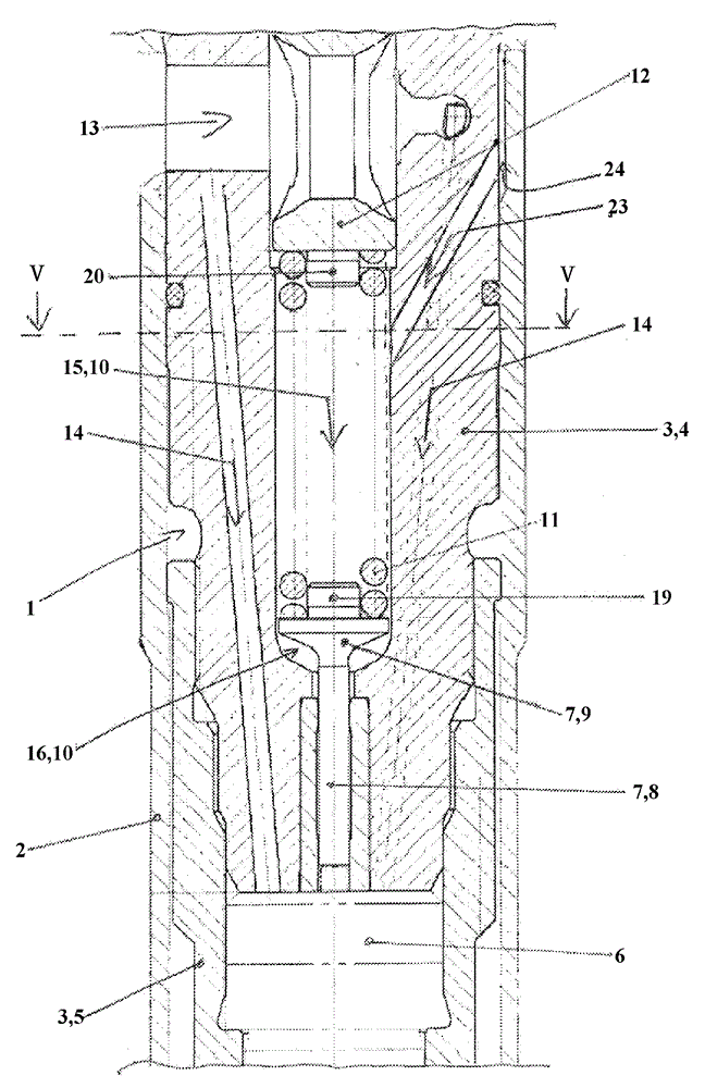
[0045] The invention here relates to a fluid-operated valve, in particular a fuel injection valve for the fuel supply of large diesel engines, preferably for the fuel supply of marine diesel internal combustion engines operating on heavy fuel oil.

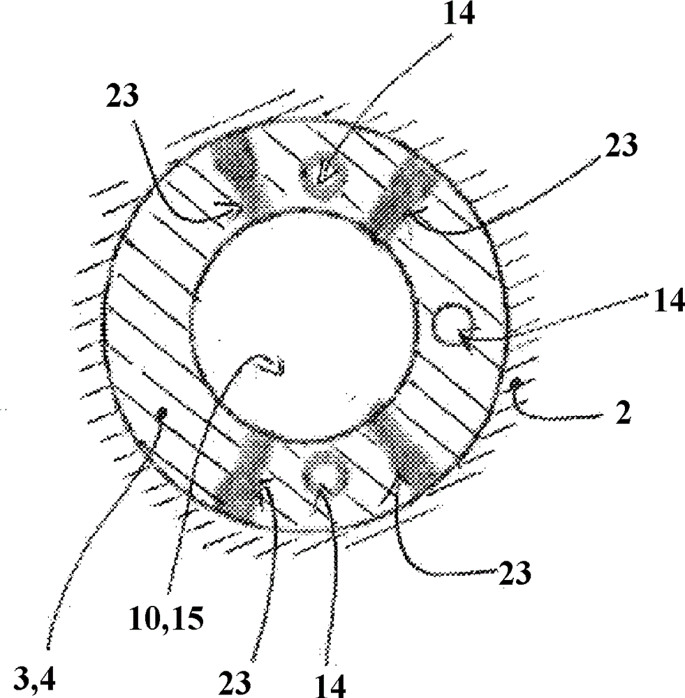
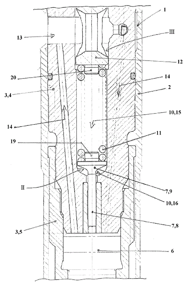
[0046] figure 1 A partial cross section through fuel injector 1 is shown in section, fuel injector 1 being arranged in receptacle 2 . The receptacle 2 can be a cylinder head of an internal combustion engine. figure 1 The fuel injector has a valve housing 3 which, in the exemplary embodiment shown, consists of two sections 4 , 5 screwed together. The valve housing 3 is in figure 1 The upper section 4 shown in is screwed into the valve housing 3 in the figure 1 In the lower section 5 shown in and extends therein segment by segment.

[0047] In the valve housing 3, in figure 1 In its lower section 5 , a valve body 6 in the form of a nozzle needle is guided, which interacts with a valve seat provided by the lower section 5 of the ...


PUM


Abstract

The present invention relates to a valve of liquid operation, especially a fuel injection valve. The valve has a valve shell, wherein in the valve shell, on one hand, a valve body interacted with a valve seat is guided, especially a nozzle needle, on the other hand, an operating element interacted with the valve body is guided, i.e., the operating element causes the valve body to be pressed into a closed position facing the valve seat through a spring force of a spring element attaching to a spring plate position of the operating element, while fluid pressure at the valve body position raises the valve body from the valve seat against the spring force of the spring element, wherein fluid leaks and gathers in a spring cavity of the valve shell for containing the spring element and can be outputted from the valve through a leakage pipeline, and wherein, at least one hole is leaded in the spring plate of the operating element for connecting a sub-cavity of the spring cavity arranged at a first side of the spring plate with a sub-cavity of the spring cavity arranged at a second side of the spring plate.

Description

technical field [0001] The invention relates to a fluid-operated valve according to the preamble of claim 1 or according to the preamble of claim 9 . Background technique [0002] The fluid-operated valve designed as a fuel injector has a valve housing which provides a valve seat and in which a valve body, which interacts with the valve seat and is designed as a nozzle needle, is guided. Furthermore, an actuating element cooperating with the valve body is guided in the valve housing in such a way that the actuating element interacts with the valve body in such a way that the actuating element is moved by the spring force of the spring element abutting against the spring plate of the actuating element The valve body is pressed into the closed position against the valve seat. If a defined fluid pressure is present on the valve body, this fluid pressure can lift the valve body from the valve seat against the spring force of the spring element. Here, the spring element of the ...

Claims


Application Information

Patent Timeline
Patent Type & Authority Applications(China)
IPC IPC(8): F02M47/02
CPCF02M47/00F02M55/008F02M61/10F02M63/04F02M2200/04F02M2200/50F02M47/022F02M61/045F02M61/12F02M61/20F02M2200/03F02M2200/46
Inventor R.迈尔C.施特尔茨勒
Owner MAN ENERGY SOLUTIONS SA
Why Eureka
Try Eureka