A hand-eye calibration method for manipulator based on active binocular vision

A technology of binocular vision and hand-eye calibration, which is applied in the direction of instruments, measuring devices, and optical devices. It can solve the problems of not very strict camera calibration accuracy, adding marker points at the end of the manipulator, and complex hand-eye calibration algorithms. It is easy to operate, The effect of simple algorithm and high precision

Active Publication Date: 2017-11-10
SHENZHEN UNIV
View PDF1 Cites 0 Cited by
  • Summary
  • Abstract
  • Description
  • Claims
  • Application Information

AI Technical Summary

Problems solved by technology

The Eye-in-Hand type is that the visual sensor is installed on the manipulator. The hand-eye calibration algorithm of this installation method is more complicated, but the camera and the manipulator control end can form a closed-loop control system. With the movement of the manipulator, the influence of the camera calibration error can be reduced. Therefore, this method is not very strict on the camera calibration accuracy.
The Eye-to-Hand type is that the vision sensor is separated from the manipulator. The vision sensor is installed somewhere outside the manipulator and does not change its position with the movement of the manipulator. The hand-eye calibration algorithm of this installation method is relatively simple, but the accuracy is limited by the camera calibration. It is manifested in the accuracy of the target point coordinates calculated by the visual sensor, so the accuracy requirements for camera calibration are very strict
The existing Eye-to-Hand manipulator hand-eye calibration method, such as the patent "Indoor Robot Vision Hand-Eye Relationship Calibration Method Based on 3D Image Sensor" (Application No.: 201410166077.6), adds a marker point at the end of the manipulator and uses a visual sensor to collect the marker The method of pointing three-dimensional coordinates to obtain the coordinate data used to calculate the hand-eye relationship matrix is ​​simple, but in some cases it is not suitable to add marker points at the end of the manipulator, such as the case where the end of the manipulator is sharp and small

Method used


Image

  • A hand-eye calibration method for manipulator based on active binocular vision
  • A hand-eye calibration method for manipulator based on active binocular vision
  • A hand-eye calibration method for manipulator based on active binocular vision

Examples


Embodiment Construction

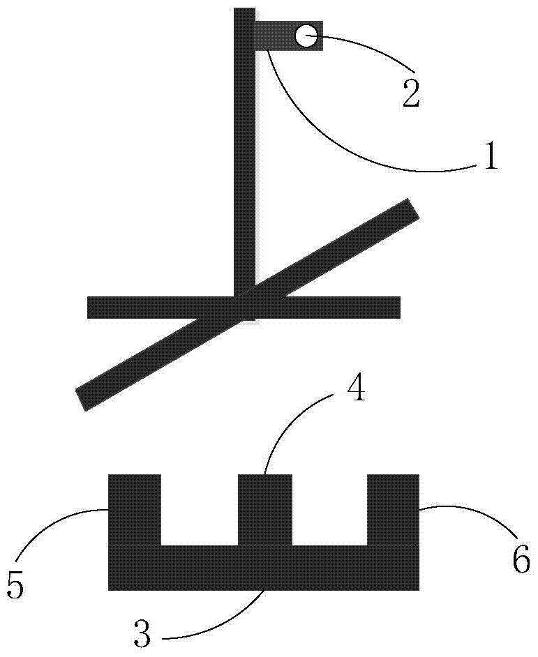
[0024] A kind of hand-eye calibration method of manipulator based on active binocular vision of the present invention, refer to figure 1 As shown, it includes a manipulator 1 and a manipulator end 2, and also includes an active binocular vision sensor 3. The active binocular vision sensor 3 consists of a binocular vision sensor left camera 5, a binocular vision sensor right camera 6 and a structured light generator 4. composition. In order to ensure that the coding pattern projected by the light structure generator 4 to the end of the manipulator can be captured by the two cameras, the structured light generator 4 is located between the left camera 5 of the binocular vision sensor and the right camera 6 of the binocular vision sensor.

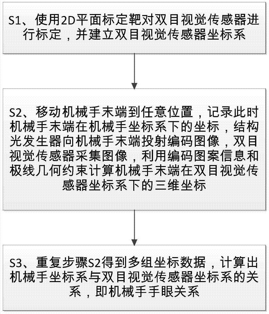
[0025] refer to image 3 As shown, a kind of hand-eye calibration method of a manipulator based on active binocular vision of the present invention specifically includes the following steps:

[0026] S1. Use the 2D plane calibration target to...


PUM


Abstract

The invention discloses a manipulator hand-eye calibration method based on active binocular vision, which comprises the following steps: S1, using a 2D plane calibration target to calibrate a binocular vision sensor, and establishing a binocular vision sensor coordinate system; S2, moving the end of the manipulator to At any position, record the coordinates of the end of the manipulator in the manipulator coordinate system at this time. The structured light generator projects a coded image to the end of the manipulator. Three-dimensional coordinates in the sensor coordinate system; S3, repeat step S2 to obtain multiple sets of coordinate data, and calculate the relationship between the manipulator coordinate system and the binocular vision sensor coordinate system, that is, the manipulator hand-eye relationship.

Description

technical field [0001] The invention relates to a hand-eye calibration method of a manipulator, in particular to a hand-eye calibration method of a manipulator based on active binocular vision. Background technique [0002] With the development of vision technology and the improvement of robot precision requirements in industry, more and more industrial robots use vision sensors as their operation and navigation tools. In order to provide navigation guidance for the manipulator, the visual sensor must first perform hand-eye calibration to obtain the positional relationship between the visual sensor and the manipulator, and then collect the coordinates of the target object in the binocular vision sensor coordinate system according to the vision sensor, and convert it into the coordinate system of the manipulator. The coordinates below provide guidance for the manipulator operation. According to the positional relationship between the visual sensor and the manipulator, the vi...

Claims


Application Information

Patent Timeline
Patent Type & Authority Patents(China)
IPC IPC(8): G01B11/00
Inventor 李东白龙彪田劲东
Owner SHENZHEN UNIV
Why Eureka
Try Eureka