Wire grid polarizer and manufacturing method thereof

A technology of a wire grid polarizer and a manufacturing method, which is applied in polarizing elements, instruments, optics, etc., can solve problems such as dark state light leakage and viewing angle defects, and achieve the effects of eliminating bad situations, eliminating dark state light leakage, and improving viewing angle defects

Inactive Publication Date: 2015-08-26
AU OPTRONICS CORP
View PDF0 Cites 3 Cited by
  • Summary
  • Abstract
  • Description
  • Claims
  • Application Information

AI Technical Summary

Problems solved by technology

However, in existing wire grid polarizers, the azimuth angles of 45 degrees, 135 degrees, 225 degrees and 315 degrees have viewing angle disadvantages, which easily lead to dark state light leakage

Method used


Image

  • Wire grid polarizer and manufacturing method thereof
  • Wire grid polarizer and manufacturing method thereof
  • Wire grid polarizer and manufacturing method thereof

Examples


Embodiment Construction

[0031] In order to make the technical content disclosed in this application more detailed and complete, reference may be made to the accompanying drawings and the following various specific embodiments of the present invention. The same signs in the accompanying drawings represent the same or similar components. However, those of ordinary skill in the art should understand that the embodiments provided below are not intended to limit the scope of the present invention. In addition, the drawings are only for illustrative purposes, and are not drawn according to their original dimensions.

[0032] The specific implementation manners of each aspect of the present invention will be further described in detail below with reference to the accompanying drawings.

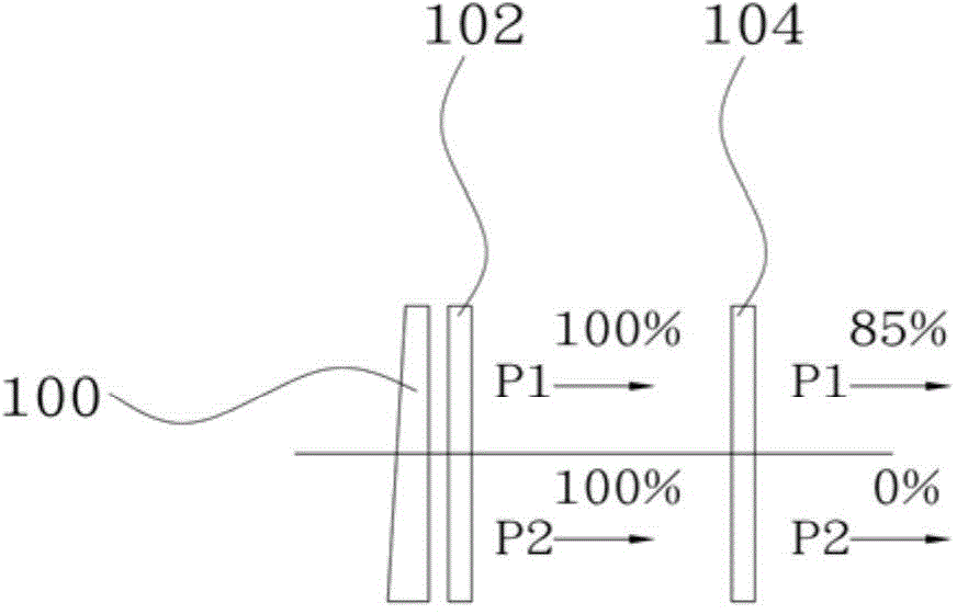
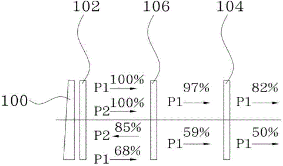
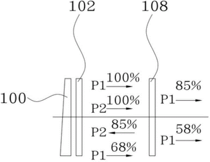
[0033] Figure 1A A schematic diagram showing the state of light transmittance when a common lower polarizer is used in the prior art, Figure 1B A schematic diagram showing the state of light transmittance when the brightness en...


PUM

PropertyMeasurementUnit
reflectanceaaaaaaaaaa
strengthaaaaaaaaaa
reflectanceaaaaaaaaaa

Abstract

The invention provides a wire grid polarizer and a manufacturing method thereof. The wire grid polarizer comprises an absorbing layer and a metal wire grid, wherein the absorbing layer comprises a base plate, multiple first bulge parts arranged on the upper surface of the base plates at intervals, aluminium wires arranged on the surfaces of the first bulge parts, and silicon dioxide layers; the metal wire grid comprises flat layers, aluminium layers arranged on the flat layers, and second bulge parts arranged on the upper surfaces of the aluminium layers at intervals; the surfaces of the silicon dioxide layers are coated with the flat layers; the second bulge parts are adopted to etch the aluminium layers so as to form a grating structure. Compared with the prior art, the overlapped double-grating structure can improve the visual angle defects of the existing wire grid polarizer and also can eliminate the bad situation of dark state light leakage.

Description

Technical field [0001] The invention relates to an inorganic polarizer, in particular to a wire grid polarizer and a manufacturing method thereof. Background technique [0002] The Wire Grid Polarizer (WGP) is composed of a diffraction grating, which has the function of making the transmitted light polarized. For example, the diffraction grating is arranged in parallel on a glass substrate with a pitch shorter than the wavelength of the light as grating lines. The multiple metal wires make the wire grid polarizer reflect the light emitted from the light source and penetrating the wire grid polarizer, the electric field vibrates in the direction parallel to the grating line, and at the same time the electric field vibrates in the direction perpendicular to the grating line The light transmitted by the light source converts the light emitted by the light source into polarized light. [0003] In the existing liquid crystal display device, the light emitted from the backlight and emit...

Claims


Application Information

Patent Timeline
Patent Type & Authority Applications(China)
IPC IPC(8): G02B5/30
CPCG02B5/3058
Inventor 林圣凱吕仁贵黄胜铭陈志强王铭瑞粘瀚升张晖谷王潍淇锺佳欣陈俊维
Owner AU OPTRONICS CORP
Why Eureka
Try Eureka