
Suction disc separation mechanism for lead storage battery plate

A lead-acid battery and separation mechanism technology, which is applied in the field of mechanical parts, can solve the problems of poor separation effect and low stability of the plates, and achieve the effects of improving stability, preventing dumping, and improving separation effect

Active Publication Date: 2015-08-26
NINGBO UNIV
View PDF8 Cites 5 Cited by
  • Summary
  • Abstract
  • Description
  • Claims
  • Application Information

AI Technical Summary

Problems solved by technology

[0004] The purpose of the present invention is to address the deficiencies of the prior art, to provide a lead-acid battery plate sucker separation mechanism, which solves the technical problems of the prior art such as low stability and poor plate separation effect

Method used


Image

  • Suction disc separation mechanism for lead storage battery plate
  • Suction disc separation mechanism for lead storage battery plate
  • Suction disc separation mechanism for lead storage battery plate

Examples


Embodiment Construction

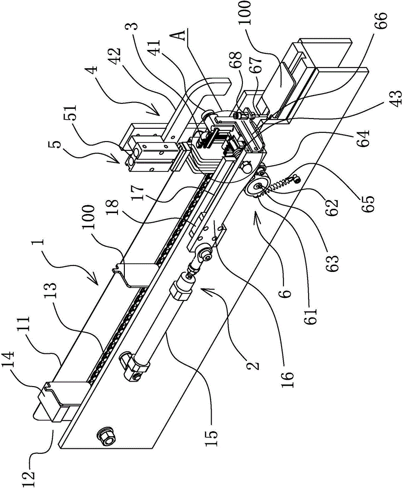
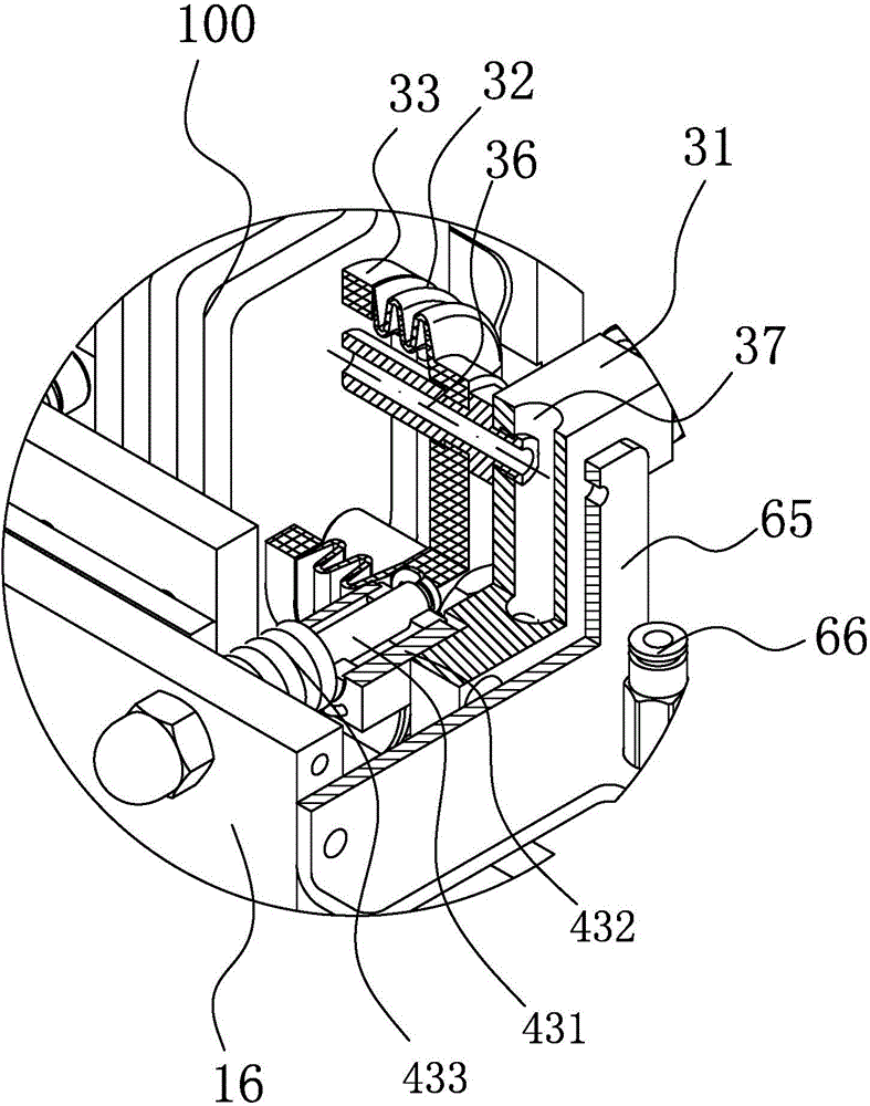
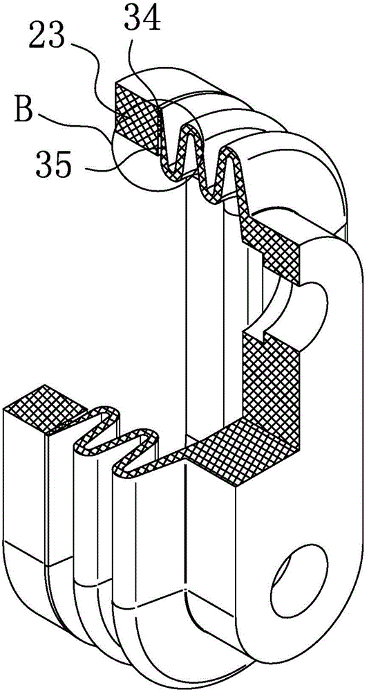
[0025] Such as Figure 1-5 As shown, a lead-acid battery plate sucker separation mechanism includes a track conveying mechanism 1 capable of transporting pole plates 100, a drive mechanism 2 is provided on the track conveying mechanism 1, and the end of the drive mechanism 2 is provided with There is a suction cup mechanism 3 that can hold and loosen the inner pole plate 100 of the rail conveying mechanism 1. The driving mechanism 2 can push the sucker mechanism 3 to move back and forth. Suction cup turning mechanism4. When working, the pole plate 100 is placed in the track conveying mechanism 1 and sent to the position where the suction cup mechanism 3 is located. The suction cup mechanism 3 is connected to a vacuum device and a compressed gas device through a pipeline. The mechanism 3 is connected to the vacuum device to suck the pole plate 100. At this time, the driving mechanism 2 pushes the suction cup mechanism 3 to move forward. When the suction cup mechanism 3 contact...


PUM


Abstract

The invention provides a suction disc separation mechanism for a lead storage battery plate, and belongs to the technical field of mechanical parts. The suction disc separation mechanism solves the technical problems of low stability, poor plate separation effect and the like in the prior art. The suction disc separation mechanism comprises a rail conveying mechanism capable of conveying the plate, wherein a driving mechanism is arranged on the rail conveying mechanism; a suction disc mechanism capable of sucking and releasing the plate in the rail conveying mechanism is arranged at the end part of the driving mechanism; the driving mechanism can push the suction disc mechanism to move back and forth; and a suction disc turnover mechanism capable of allowing the suction disc mechanism to perform turnover action is arranged on the rail conveying mechanism. The suction disc separation mechanism is simple, and reliable and stable in working.

Description

technical field [0001] The invention belongs to the technical field of mechanical parts, and relates to a sucker separation mechanism, in particular to a lead storage battery polar plate suction cup separation mechanism. Background technique [0002] A suction cup is a pendant that uses the difference in internal and external air pressure to adsorb on an object, or a tool for grabbing an object, also called a vacuum suction cup. Vacuum suction cup is a technology that maintains the attachment of two objects without separation through vacuum. It can be divided into industrial applications and folk applications. ", with the realization of automation and mechanization. [0003] In the battery production process, multiple plates are placed together in the early stage of the production process. However, in the production process, it is necessary to separate and position these polar plates placed together individually. Manual operation is inefficient and labor-intensive. At pr...

Claims


Application Information

Patent Timeline
IPC IPC(8): H01M10/04B65G47/90
CPCB65G47/90H01M10/0404Y02P70/50
Inventor 葛先越葛国平
Owner NINGBO UNIV
Learn More