Rapid grounding rod with plugging device, suitable for temporary opeartion

A technology of plug-in device and grounding rod, which is applied in the direction of connecting contact materials, etc., can solve the problems of affecting timeliness, difficulty in pulling out, and increase in resistance value, and achieves the advantages of easy disassembly and installation, improved protection effect, and extended service life Effect

Inactive Publication Date: 2015-08-26
NORTHEAST GASOLINEEUM UNIV
View PDF6 Cites 7 Cited by
  • Summary
  • Abstract
  • Description
  • Claims
  • Application Information

AI Technical Summary

Problems solved by technology

This method of pulling out is a helpless move, which is laborious and affects timeliness. There have even been incidents where the grounding rod was nailed too deep and could not be pulled out. The logging tool winch was able to leave the well site by cutting the grounding wire and abandoning the grounding rod.
In a nutshell, the existing grounding rods for well logging have the following problems: (1) single heavy hammer nailing method, if the heavy hammer is lost during well logging construction, it will not be able to enter the ground, which directly affects the inability to perform well logging operations; ( 2) Restricted by the timeliness of logging operations, it is difficult to pull out in a short time, especially in the winter operation period; (3) The ground wire and ground rod are the simplest winding contact connection, which is not laborious and easy to oxidize. Rust increases resistance and reduces conductivity

Method used


Image

  • Rapid grounding rod with plugging device, suitable for temporary opeartion
  • Rapid grounding rod with plugging device, suitable for temporary opeartion
  • Rapid grounding rod with plugging device, suitable for temporary opeartion

Examples


Embodiment Construction

[0017] The present invention will be further described below in conjunction with accompanying drawing:

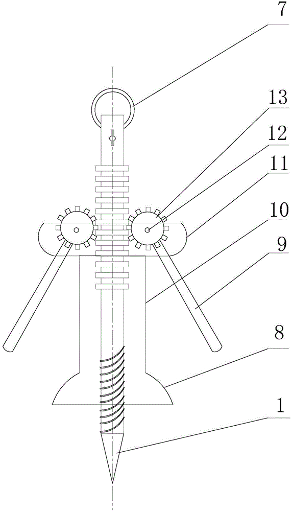
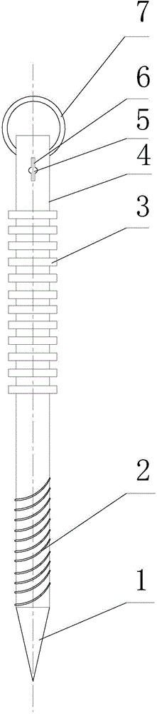
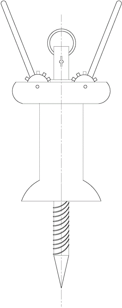
[0018] Depend on Figure 1 to Figure 4 As shown, this kind of fast grounding rod with its own plug-in device suitable for temporary operations includes a rod-shaped grounding rod body 4, which is unique in that: the bottom end of the grounding rod body 4 is a cone segment 1, and the Above the cone section 1 is an externally threaded section 2, and the top of the ground rod main body 4 is provided with a threading groove 6 through which a nickel sealing hole 5 is opened in the middle section of the threading groove. Above the threading groove, a hard insulating ring 7 is fixed through the main body of the grounding rod; on the main body of the grounding rod, it is fixed at equal intervals between the lower part of the threading groove and the upper part of the external thread section 2 There are several nested ring bodies 3, the longitudinal section of the convex part of th...


PUM


Abstract

Provided is a rapid grounding rod with a plugging device, suitable for temporary opeartion. A main objective is to solve problems that a grounding rod used in existing logging operation cannot easily be rapidly fixed and detached. The rapid grounding rod is characterized in that on a grounding rod main body, between the lower part of a threading groove and the upper part of an external thread segment, a plurality of embedded circular rings are fixed at equal interval, the longitudinal section of the bulge part of the embedded circular ring is in a trapezoid shape, and the plurality of embedded circular rings form a left straight-toothed rack and a right straight-toothed rack from top to bottom. The grounding rod also comprises a support sleeve with a support cylinder skirt base. The top end of the support sleeve is welded and fixed with two vertical ear plates. A pair of straight toothed spur gear plates are respectively fixed between the two vertical ear plates through gear plate bearings. The grounding rod main body is in the support sleeve. The straight teeth on the pair of straight toothed spur gear plates are respectively meshed with the left straight-toothed rack and the right straight-toothed rack which are formed by the plurality of embedded circular rings. The pair of straight toothed spur gear plates are respectively fixedly provided with symmetric insulation compression bars.

Description

technical field [0001] The invention relates to a grounding rod which is suitable for the drawworks of the well logging instrument in the field of oil field logging when implementing the logging operation. Background technique [0002] The grounding rod is a commonly used protection device in the operation of the power system. Its main function is to prevent lightning strikes and lead high-voltage electricity into the ground. Easy to pull out for long-term and stable protection. In well logging operations, the ground rod is also an indispensable device. According to CNPC's logging operation instructions and operating standard documents, the logging tool drawworks must use ground rods when performing logging operations, and shuttle buses or camping vehicles are used as supplementary vehicles for transporting logging instruments, auxiliary equipment and HSE equipment. It is a temporary rest place between wellhead work during the stay. No matter whether the power is connected...

Claims


Application Information

Patent Timeline
IPC IPC(8): H01R4/66
Inventor 吴佳忆张美玲包燚王利国王静杨春来
Owner NORTHEAST GASOLINEEUM UNIV
Why Eureka
Try Eureka