
Rotor structure of surface-mounted high-speed permanent magnet motor

A rotor structure, permanent magnet motor technology, applied in the magnetic circuit shape/pattern/structure, magnetic circuit rotating parts and other directions, can solve the problems of poor gas flow characteristics, increased initial rotor imbalance, etc., to achieve enhanced flow, good Initial balance, effect of increasing heat dissipation

Inactive Publication Date: 2015-08-26
ZHEJIANG UNIV
View PDF8 Cites 3 Cited by
  • Summary
  • Abstract
  • Description
  • Claims
  • Application Information

AI Technical Summary

Problems solved by technology

However, the spiral groove on the outer surface of the protective cover shown in this patent is a non-straight groove, the flow characteristics of the gas are poor, and it is difficult for the wind to enter from the entrance of the spiral groove on the outer surface of the protective cover. In addition, the inappropriate design of the spiral groove will increase the initial imbalance of the rotor

Method used


Image

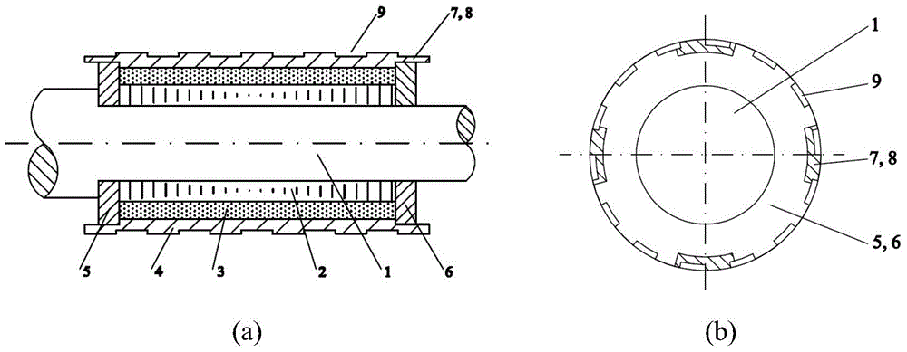
  • Rotor structure of surface-mounted high-speed permanent magnet motor
  • Rotor structure of surface-mounted high-speed permanent magnet motor

Examples


Embodiment 1

[0018] Such as figure 1 As shown, it includes a rotating shaft 1, a rotor core 2, a permanent magnet 3, a protective sleeve 4, a left end flange 5 and a right end flange 6. The two ends of the protective sleeve 4 are circumferentially symmetrically distributed with a plurality of keys 7 beyond the outer end surfaces of the left flange 5 and the right flange 6, and the left flange 5 and the right flange 6 also have keys at both ends of the protective sleeve 4. 7, the outer surface of the protective sheath 4 is evenly distributed in the circumferential direction with a plurality of grooves 9 that form a certain angle with the busbar of the protective sheath 4. The rotor core 2, the left flange 5 and the right flange 6 are set on the rotating shaft 1, and the steps on the left side of the shaft are used for axial positioning, and the permanent magnet 3 is set on the rotor core between the left flange 5 and the right flange 6 On the outer circle of 2, protective cover 4 is enclos...

Embodiment 2

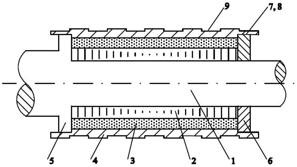
[0022] Such as figure 2 As shown, it includes rotating shaft 1, rotor core 2, permanent magnet 3, protective cover 4, left end flange 5 and right end flange 6, and a step is designed at the left end of the installation position of rotor iron core 2 to form left end flange 5. The two ends of the protective sleeve 4 are circumferentially symmetrically distributed with a plurality of keys 7 beyond the outer end surfaces of the left flange 5 and the right flange 6, and the left flange 5 and the right flange 6 are also designed with keys at both ends of the protective sleeve 4. 7, the outer surface of the protective sheath 4 is evenly distributed in the circumferential direction with a plurality of grooves 9 that form a certain angle with the busbar of the protective sheath 4.

[0023] When installing, first put the rotor core 2 on the rotating shaft 1, and use the left end flange 5 on the shaft for axial positioning. On the outer circle of the rotor core 2 with 3 permanent magnet...


PUM


Abstract

The invention discloses a rotor structure of a surface-mounted high-speed permanent magnet motor. The structure comprises a protective sleeve, a rotor core, a rotating shaft and a permanent magnet. Two ends of the rotor core are provided with two flanges respectively. Two ends of the protective sleeve are symmetrically provided with a plurality of limiting keys along a circumferential direction. The flanges are provided with a plurality of limiting grooves which are cooperated with the limiting keys. According to the rotor structure of the invention, the keys which are arranged on two ends of the protective sleeve are cooperated with the grooves on the left end flange and the right end flange so as to limit circumferential and axial movement of the protective sleeve under a working state; fixation of the permanent magnet is reliable; a temperature of the protective sleeve during shrinkage fit is reduced and installation is simple and convenient. The keys of the two ends of the protective sleeve, which exceed external end surfaces of the left end flange and the right end flange, enhance a heat dissipation effect of airflow. Because of circumferential grooves on an external surface of the protective sleeve, eddy-current losses are reduced and a cooling effect of a rotor is increased. The grooves are symmetrically distributed on the external surface of the protective sleeve along a circumferential direction so that the rotor possesses good initial equilibrium.

Description

technical field [0001] The invention belongs to the technical field of permanent magnet motors, and in particular relates to a rotor structure of a surface-mounted high-speed permanent magnet motor. Background technique [0002] The reliable fixation of permanent magnets on the rotor of surface-mounted high-speed permanent magnet motors is very important for the normal operation of high-speed permanent magnet motors. In the working process of the surface-mounted high-speed permanent magnet motor, the permanent magnet on the rotor is subjected to a huge centrifugal force. In order to prevent the permanent magnet from falling off, circumferential and axial movement during operation, etc., which seriously affect the normal operation of the motor Appears, need to carry out reliable fixation to permanent magnet. At present, the more commonly used permanent magnet fixing method for surface-mounted high-speed permanent magnet motors is to heat-fit a high-strength alloy or composit...

Claims


Application Information

Patent Timeline
Patent Type & Authority Applications(China)
IPC IPC(8): H02K1/27H02K1/32
Inventor 祝长生
Owner ZHEJIANG UNIV
Learn More